I I I I I I I I I I I I I I I I I I I I I I I I I I I I I I I I I I I I I I I I I I I I I I I I I I I I I I I I II I I I I I I II
I‘
GENERAL INFORMAiiON
l-5
9
.
10
.
II
.
Measurement criteria are defined by the terms “standard” and “limit”.
A measurement falling within the “standard” range indicates that the applicable part or parts are ser-
vicea ble.
“Limit” should be thought of as an absolute value.
A measurement which is outside the “limit” indicates that the applicable part or parts must be either
repaired or replaced.
Components and parts are listed in the singular form throughout the Manual.
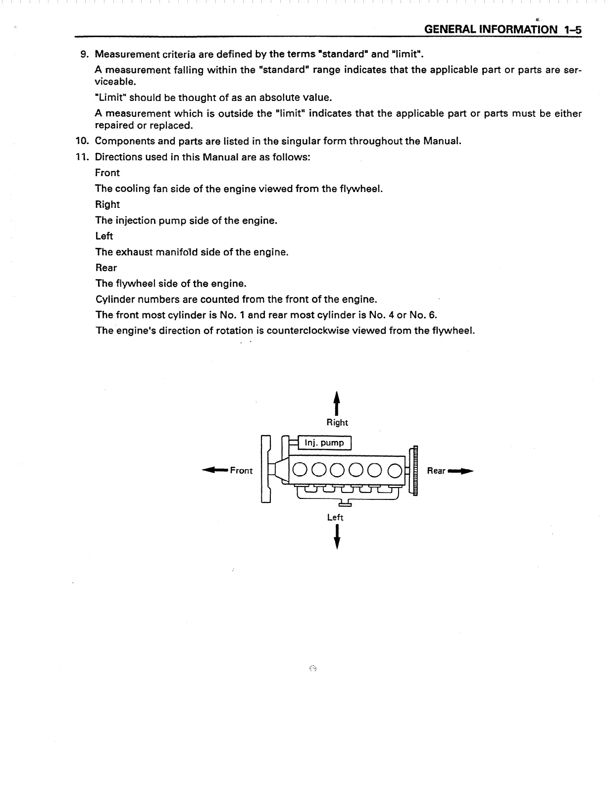
Directions used in this Manual are as follows:
Front
The cooling fan side of the engine viewed from the flywheel.
Right
The injection pump side of the engine.
Left
The exhaust manifold side of the engine.
Rear
The flywheel side of the engine.
Cylinder numbers are counted from the front of the engine.
The front most cylinder is No. 1 and rear most cylinder is No.
4
or No. 6.
The’engine’s direction of rotation is counterclockwise viewed from the flywheel.
. -
b Front
t
Right
Rear W
Left
+
 Loading...


