iSYSTEM, March 2017 8/66
Power Supply
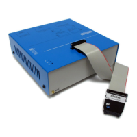
A round 3-pin power connector is located on the rear of the iC5500 base unit.
Power connector pinout, view from the rear of the Emulator
The iC5500 unit accepts a wide input voltage range from 10V to 24V DC, thus enabling the Emulator to work
also with a 12V or 24V car battery. Power consumption is up to 15W (iC5500 without optional I/O module).
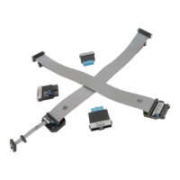
The necessary power supply (IC30000-PS) comes along the iC5500 unit.
IC30000-PS
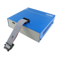
An optional 12V power supply for Car (cigarette lighter) plug can be ordered under the IC30000-PS-CAR12V
ordering code.
IC30000-PS-CAR12V
Note: Use only original iSYSTEM accessories for powering the iC5500. If you wish to use a power supply
different from the delivered one, please consult with iSYSTEM first.
iC5500 System Power On / Power Off Sequence
In general, the iC5500 Analyzer and the target must be in the same power state. Both must be on, or both off.
Level translators on the DTM module go high-Z when either emulator or target (TAR_VREF) supply is off.
Therefore, it is recommended to use ‘Vref’ setting for the ‘Debug I/O levels’ in winIDEA ‘Hardware/Emulation
options/Hardware’ tab. Note, this is not applicable when using Hot Attach operation.
 Loading...