iSYSTEM, March 2017 7/66
Connectors
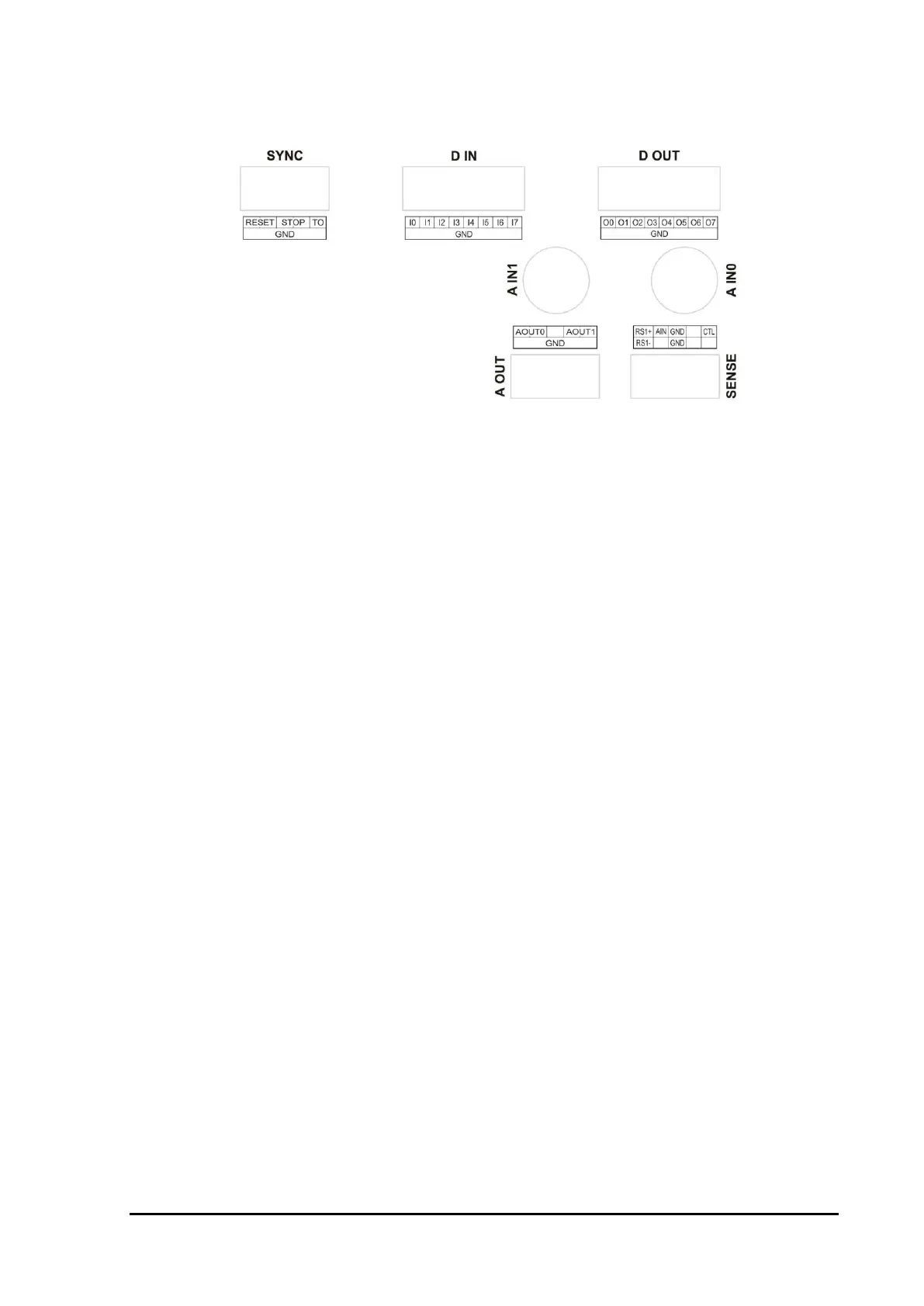
iC5500 I/O Module Connectors’ Pinout
10-pin header for the System Port.
16-pin header for 8 digital inputs.
16-pin header for 8 digital outputs.
10-pin header for 2 analog outputs.
2 BNC connectors for 2 analog inputs.
10-pin header for Power Measurement Port.
All connectors, except the BNCs, are standard Berg 2.54mm / 100mils raster.
For analog inputs, standard scope probes can be used.
For more details on I/O module and its use, refer to a separate standalone document titled I/O Module user’s
manual.