Debug Adapter
Depending on the Target microcontroller, iSYSTEM supplies one of two different types of
connection system to link the BlueBox hardware with the Target microcontroller:
·
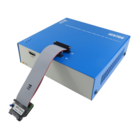
Single 40-pin ribbon cable together with a debug adapter suited to the debug connector of
the Target development board. The debug adapter should be connected to one end of the
25-cm, 40-pin ribbon cable (included in your BlueBox delivery), with the other end being
connected to the DTM #1 socket; or
·
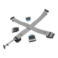
Two ribbon cables, one 30-pin and one 40-pin, with a permanently fitted to the debug
adapter.
1. Connect the 40-pin ribbon cable connector to the DTM #1 socket.
The ribbon cable must always be guided towards the BlueBox front panel with the red wire on
the side of the ‘#1’ marking (optional ‘#2’). Align the orientation key of the cable connector with
the notch on the BlueBox’s 40-pin socket – the wider of the two sockets. Carefully press the
cable connector straight down, keeping the connector parallel to the upper face of the BlueBox,
until the side latches lock.
(Optional) The second connection system consists of two pin ribbon cables, one 30-pin and
one 40-pin, with a permanently fitted debug adapter. For the second connection repeat step 1.