Italfarad S.p.A. Via IV Novembre n.1 40061 Minerbio Bologna Italy Tel.+39 051 6618311 Fax +39 051 6605594 E-mail: italfarad@italfarad.com Web:www.italfarad.com 13
1. General remarks
The automa•c power factor correc•on equipments type PF
are used to keep the power factor to an average value higher
than an expected one.
The regula•on is obtained by means of a suitable electronic
regulator of reac•ve power with high sensibility and
precision.
The equipment consist of capacitors banks which are
connected and disconnected automa•cally, depending on
the reac•ve power required by the load, by mean of special
contactors.
The capacitors are single phase or three phase type,
provided with discharge resistors and overpressure safety
device, in compliance with the IEC Standards.
The enclosure is of steel cabinet, painted with epoxy resins
with minimum protec•on degree IP30.
2. Connec•on to the network
The three phases of the network must be connected
respec•vely to R (L1), S (L2) and T (L3) terminals onto the
main switch.
For earthing the bar on the right side of the equipment, or
the earth terminal, must be used.
Terminals K (S1) and L (S2) must be connected to the
secondary of a Current Transformer (CT) with secondary
current 5A connected on the phase R (L1) (see Fig.1).
In order to work properly the equipment must be connected
as indicated in Fig.1; on the same page some typical
connec•on mistakes are shown.
Index Page
General remarks 13
Connec!on to the network 13
Start and use
13
Control of the automa!c opera!on 14
Maintenance 14
Connec!on diagram 15
CT Connec!on place 15
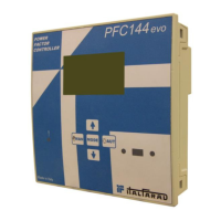
Power factor controller PFC96evo 16
Power factor controller PFC144evo 19
Maintenance log 22
3 Start and use
ATTENTION"
Before switching to the equipment on, check the correct
•ghtening of all the connec•ons. Repeat this opera•on
periodically.
At the first switch on, the controller will show the indica•on
“Ct”.
Press “+“ and “-” (controller type PFC) or “↑” and
“↓” (controller type PFCevo) to set the value of the primary
current of the CT. Press manual/automa•c bu#on to validate
the value.
If regulator is correcty installed the equipment connects and
disconnects automa•cally the capacitor banks according to
the load varia•on; in this case the number of banks
connected is evidence by the leds STEP on the regulator.
If during the first installa•on, the regulator of reac•ve power
would show a capaci•ve load and no banks have been
connected, the CT has been installed on the wrong phase
(see fig. 1 and 2).
In order to avoid that the limits of overtemperature are
passed inside the cabinet, the reac•ve power regulator starts
the fan when temperature is higher than the threshold.
If the temperature inside the cabinet, in spite of the cooling
due to the fan opera•on, reaches 50°C, all the banks are
disconnected and a remote signal alarm is ac•vated.
In the equipments which are equipped with SPC2 device, the
ven•la•on and the alarm signal are generated by SPC2.
ATTENTION!
Using the manual control please wait at least 1 minute
before connec•ng the same bank again.