Power Factor Controller PFC144evo
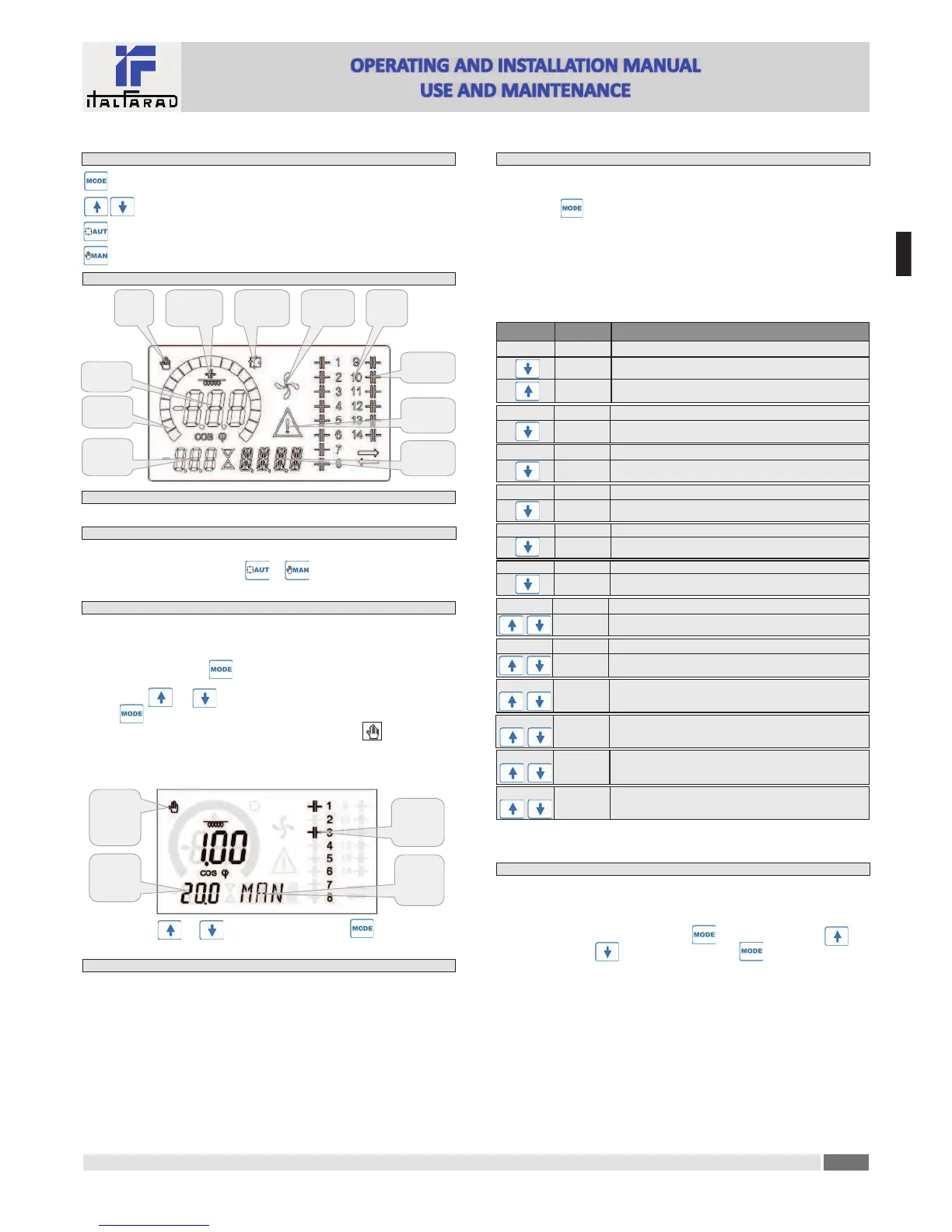
Front keyboard
Key - Used to select among available measurements. Used also to access programming menus.
keys - Used to set values and to select steps.
key - Used to select automa!c opera!ng mode.
key - Used to select manual opera!ng mode.
Display indica!ons
Output
status
Cooling fan
status
Secondary
display
Ac!ve
alarm
Automa!c
mode
Manual
mode
Main
Induc!ve /
capaci!ve
Bar
Alphanumeric
display
Step
Opera!ng modes
There are two possible opera!ng modes, listed below:
MAN and AUT modes
· The icons AUT and MAN indicate the opera!ng mode automa!c or manual.
· To change the mode, press and hold the or bu"on for 1 sec.
· The opera!ng mode remains stored even a#er removing and reapplying the power supply voltage.
MAN mode
· When the unit is in manual mode, you can select one of the steps and manually connected or
disconnect it.
· In addi!on to the speci$c icon, the alphanumeric display shows MAN in order to highlight the
manual mode condi!on. Press to view the other measurements as usual.
· While the display shows MAN, it is possible to select the step to be switched on or o%. To select a
step, use the or bu"ons. The selected step will &ash quickly.
· Press to ac!vate or deac!vate the selected step.
· If the selected step has not yet exhausted the reconnec!on !me, the icon will &ash to
indicate that the transac!on has been accepted and will be conducted as soon as possible.
· Manual con$gura!on of the steps is maintained even when the power supply voltage is removed.
When the power returns, the original state of the steps is restored.
MAN
mode
icon
Connected
steps
Tot kvar
inserited
in MAN
Manual step
selec!on
enabled
Select step Change step status
AUT mode
·
In automa!c mode, the controller calculates the op!mum con$gura!on of capacitor steps in
order to reach the set cosø.
· The selec!on criteria takes into account many variables such as: the power of each step, the
number of opera!ons, the total !me of use, the reconnec!on !me, etc.
· The controller displays the imminent connec!on or disconnec!on of the steps with the &ashing
of their iden!$ca!on number (le#). The &ashing can last in cases in which the inser!on of a step
is not possible due to the reconnec!on !me (discharge !me of the capacitor).
· The device ini!ates automa!c correc!ons when there is an average reac!ve power request
(delta-kvar) higher than 50' of the smallest step, and the measured cosø is di%erent from the
setpoint.
Measures
·
The PFC144evo controller provides a set of measurements displayed on the alphanumeric
display, in conjunc!on with the current cosø that is always displayed on the main display.
· Press the key to scroll through the measures in rota!on.
· A#er 30 seconds without pressing any bu"ons, the display automa!cally returns to the default
measurement de$ned by P.47.
· If P.47 is set on the ROT, then the measures rotate automa!cally every 5 seconds.
· At the bo"om of the list of measures it is possible to set the setpoint of the cosø, ac!ng on the
same value set with P.19.
· Below is a table with the measurements displayed.
Voltage V
RMS voltage of the plant current.
V HI Maximum voltage value measured.
Measure Icon Descrip!on
Delta-kvar Δkvar
Kvars needed to reach the cosø setpoint. If delta-kvar is posi!ve
cpacitors need to be inserted, if nega!ve to be disconnected.
kvar Total kvar of the plant.
ΔSTEP Number of equal steps to achieve the target power factor.
Current A RMS current of the plant voltage.
A HI Maximum current value masured.
Weekly PF WPF Weekly average power factor.
PF Instantaneous total power factor.
THD cap. THDC Capacitors total harmonic distor!on (THD) in current.
TC.HI Maximum THD value measured.
Temperature °C °F Temperature of internal sensor.
°CHI
°FHI
Maximum temperature value measured.
Voltage THD THDV Total harmonic distor!on % (THD) of plant voltage.
VH02…
...VH15
% voltage harmonic content from 2.nd up to 15.th order
Current THD THDI Total harmonic distor!on % (THD) of plant current.
IH02…
…IH15
% Current harmonic content from 2.nd up to 15.th order
Cosø setpoint
IND
CAP
Se"ng of desired cosø setpoint (same as P.19).
Step power
% ❶Step residual power, as a percentage of the set rated power.
Step counter
OPC ❶Opera!on counter of the step.
Step hours
H ❶Hour meter of the step inser!on.
❶These measures are shown only if the Step trimming func!on is enabled (P.25=ON) and the
advanced password is enabled and entered.
Keypad lock
·
A func!on to exclude all modifica!on to opera!ng parameters can be enabled; measurement
viewing is s!ll provided in any case.
· To lock and unlock the keypad, press and keep key pressed. Then press the key
three !mes and the key twice and a&er that release
· The display will show LOC when the keypad is locked and UNL when it is unlocked.
· When the lock is enabled, it is not possible to make the following opera!ons:
à Opera!on between automa!c and manual mode
à Access to set-up menus
à Change of cosø set-point
· By a'emp!ng to conduct the above opera!ons, the display will view LOC to indicate the locked
keypad state.
E
N
 Loading...