Power Factor Controller PFC96evo
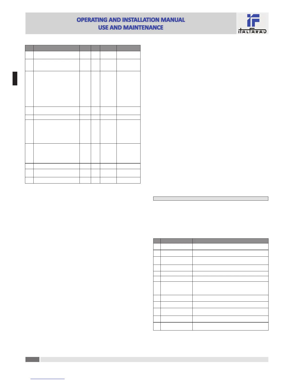
COD DESCRIPTION PSW UoM DEF RANGE
P.45 Maintenance interval Adv h
9000
8760(**)
1 - 30000
P.46 Bar-graph func!on Usr Kvar ins/tot
Kvar ins/tot
Corr a"/nom
Delta kvar a"/tot
P.47 Default auxiliary measure Usr Week TPF
Deltakvar
V
A
Week TPF
Cap. Current
Temp
THDV
THDI
ROT
P.48 Backlight flashing on alarm Usr OFF
OFF
ON
P.49 Serial node address Usr 01 01-255
P.50 Serial speed Usr bps 9.6k
1.2k
2.4k
4.8k
9.6k
19.2k
38.4k
P.51 Data format Usr 8 bit – n
8 bit, no parity
8 bit, odd
8bit, even
7 bit, odd
7 bit, even
P.52 Stop bits Usr 1 1-2
P.53 Protocol Usr
Modbus
RTU
Modbus RTU
Modbus ASCII
P.54 Number of inser!ons for maintenance Adv kcnt OFF OFF/1...60
P.21 – If set to OFF, password management is disabled and anyone has access to the se"ngs and
commands menu.
P.22 – With P.21 enabled, this is the value to specify for ac!va!ng user level access. See Password
access chapter.
P.23 – As for P.22, with reference to Advanced level access.
(*) Available value only if the controller is not installed on the ITALFARAD cabinet
P.24 – Number of phases of the power correc!on panel.
P.25 - Enables the measurement of the actual power of the step, performed each !me they are
switched in. The measure is calculated, as the current measurement is referred to the whole
load of the plant. The measured power of the steps is adjusted (trimmed) a#er each switching
and is displayed on the step life sta!s!c page. When this func!on is enabled, a 15 sec pause is
inserted between the switching of one step and the following, necessary to measure the
reac!ve power varia!on.
P.26 – P.27 - Tolerance around the setpoint. When the cosø is within the range delimited by these
parameters, in AUT mode the device does not connect / disconnect steps even if the
delta-kvar is greater than the smallest step.
P.28 - Selec!ng mode of steps inser!on.
Standard mode - Normal opera!on with free selec!on of the steps
Linear mode - the steps are connected in progression from le# towards right only following
the step number and according to the LIFO (Last In First Out) logic. The controller will not
connect a step when the system steps are of different ra!ngs and by connec!ng the next step,
the set-point value would be exceeded.
P.29 - Setpoint used when the system is genera!ng ac!ve power to the supplier (with nega!ve ac!ve
power / power factor ).
P.30 - Disconnec!on sensi!vity. Same as the previous parameter but related to disconnec!on. If set
to OFF the disconnec!on has the same reac!on !me of connec!on set with the previous
parameter.
P.31 - If set to ON, when switching from AUT mode to MAN mode, steps are disconnected in
sequence.
P.32 – Trip threshold for the capacitors overload protec!on (alarm A08), that will arise a#er a
integral delay !me, inversely propor!onal to the value of the overload.
Note: You can use this protec!on only if the capacitors are not equipped with filtering
devices such as inductors or similar.
P.33 - Threshold beyond which the integral delay for tripping of the overload alarm is zeroed,
causing the immediate interven!on of the A08 alarm.
P.34 – P.35 – Data of VTs eventually used in the wiring diagrams.
P.36 – Unit of measure for temperature.
P.37 – P.38 - Start and stop temperature for the cooling fan of the panel, expressed in the unit set
by P.36. The cooling fan is started when the temperature is >= to P.37 and it is stopped
when it is < than P.38.
P.39 - Threshold for genera!on of alarm A08 Panel temperature too high .
P.41 - Maximum voltage alarm threshold, referred to the rated voltage set with P.07, beyond which
the alarm A06 Voltage too high is generated.
P.42 - Undervoltage alarm threshold, referred to the rated voltage set with P.07, below which the
alarm A05 voltage too low is generated.
P.43 - Maximum installa!on voltage THD alarm threshold, beyond which the alarm A10 THDV too high
is generated.
P.44 – Maximum installa!on current THD alarm threshold beyond which the alarm A11 Current THD
too high is generated.
P.45 – Maintenance interval in hours. When it is elapsed, the alarm A12 Ordinary maintenance will
be generated. The hour count increments as long as the device is powered. (**) If the control-
ler is installed on the ITALFARAD cabinet
P.46 – Func!on of the semi-circular bar-graph.
Kvar ins/tot: The bar graph represents the amount of kvar actually inserted, with reference
to the total reac!ve power installed in the panel.
Curr act/nom: Percentage of actual plant current with reference to the maximum current of
the CT.
Delta kvar: bar graph with central zero. It represts the posi!ve/nega!ve delta -kvar needed to
reach the setpoint, compared to the total kvar installed.
P.47 – Default measure shown on the secondary display. Se"ng the parameter to ROT, the different
measures will be shown with a sequen!al rota!on.
P.48 – If set to ON, the display backlight flashes in presence of one or more ac!ve alarms.
P.49 – Serial (node) address of the communica!on protocol.
P.50 – Communica!on port transmission speed.
P.51 – Data format. 7 bit se"ngs can only be used for ASCII protocol.
P.52 – Stop bit number.
P.53 – Select communica!on protocol.
P.54 - Defines the number of the step (considering the step that has the highest count) beyond which
the maintenance alarm A12 is generated. This parameter should be used as an alterna!ve to
P.45. If both P.45 and P.54 are set to a value other than OFF, then P.45 has priority.
Alarms
· When an alarm is generated , the display will show an alarm icon, the code and the descrip!on of
the alarm in the language selected.
· If the naviga!on keys in the pages are pressed, the scrolling message showing the alarm indica!ons
will disappear momentarily, to reappear again a#er 30 seconds.
· Alarms are automa!cally rese&ed as soon as the alarm condi!ons that have generated them
disappear.
· In the case of one or more alarms, the behaviour of the PFC96evo regulator depends on the
proper•es se"ngs of the ac!ve alarms.
COD ALLARME DESCRIPTION
A01 Undercompensa•on
In automa•c mode, all the available steps are connected but the
cosø is s•ll more induc•ve than the setpoint.
A02 Overcompensa•on
In automa•c mode, all the steps are disconnected but the cosø is
s•ll more capaci•ve than the setpoint.
A03 Current too low
The current !owing in the current inputs is lower than minimum
measuring range.
This condi•on can occour normally if the plant has no load.
A04 Current too high
The current !owing in the current inputs is lower than minimum
measuring range.
A05 Voltage too low
The measured voltage is lower than the threshold set with P.42.
A06 Voltage too high
The measured voltage is higher than the threshold set with P.41.
A07 Capacitor current overload
The calculated capacitor current overload is higher than threshold
set with P.32 and P.33. A"er the alarm condi•ons have
disappeared, the alarm message remains shown for the following
5 min or un•l the user presses a key on the front.
A08 Temperature too high
The panel temperature is higher than threshold set with P.39.
A09 No-Voltage release
A no-voltage release has occurred on the line voltage inputs,
las•ng more than 8ms.
A10 Voltage THD too high
The THD of the plant voltage is higher than the threshold set with
P.43.
A11 Current THD too high
The THD of the plant current is higher than the threshold set with
P.44.
A12
Ordinary maintenance
requested
The maintenance interval set with P.45 has elapsed. To reset the
alarm use the command C.01 (see Command menu).
For further information, the complete user manual is available in our web site.
E
N
 Loading...