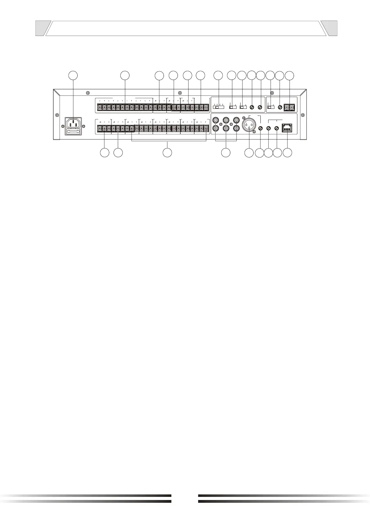
16. AC INLET
Connect to the supplied power cord.
17. Strong cut relay control output "alarm
/normal switch" in the alarm state, the
output DC 24 V level
18. Out mix music page voice
19. Out signal music
20. Remote paging output
21. CONTACT PLAY MESSAGE 1 OR 2
The third message is activated by
Microphone base directly.
22.SWITCH REC MESSAGE:
OFF, 1, 2, 3 .
REC MESSAGE switch to 1,2,3,
1,2,3 represent select storage;
When the switch is in the "OFF",
it means not record
23.SWITCH MESSAGE 1
TIME / CONTINUOS
- 1 TIME:
The recorded message plays only
Once
- CONTINUOS:
The recorded message plays
continuously till the message
contact is kept closed.
NOMENCLATURE AND FUCTIONS
4.2 REAR PANEL
16 17
38
35
18
19 20 21
22
23
24
25
26
27
28 29
36
34
33
32
31
30
24. Switch microphone alarm/normal
the mixer could work without
microphone console BMD6;A simple
microphone base with priority contact
could be connected to XLR microphone
input)
- ALARM:
The voice is simultaneously
distributed in all the 6 zones
- NORMAL:
The voice is distributed only in the
zone selected with front panel
Buttons
25. Volume REC message
26. Volume play message
27. Phantom power select switch
28. Chime volume control
29. Priority control port for BGM and internal chime
30. Remote microphone input interface (RJ 4 5)
. Background music signal input
31. Remote microphone volume control
32. Remote microphone gain adjustment
33. Local microphone gain adjustment
34. Microphone input XLR balanced
35. Audio source interface
36. OUT ZONE (1~6)
37. Emergency signal input audio source
38
7
MUSIC OUT
~230V 50Hz T1AL 250V
PRIORITY
TAPE
CD
TUNER
MICRO
CONSOL
GAIN GAIN
CONSOL
VOLUME
VOLUME
CHIME
OFF
12
3
REC
MESSAGE
1 TIME
CONTINUOS
MESSAGE
NORMAL
ALARM
VOL.PLAY
MESSAGE
VOL.REC
MIC
+48V
PHANTOM
ZONE 6 OUT ZONE 5 OUT ZONE 4 OUT ZONE 3 OUT ZONE 2 OUT ZONE 1 OUT OPEN RELE ININ COM ZONE
COM NO1 NO2
PLAY MESSAGE
MIX MUSIC-PAGE OUT
PAGE OUTRELE ZONE CONSOL OUT
1 2
3
4
5
6
37
 Loading...