4.2 Rear panel function description
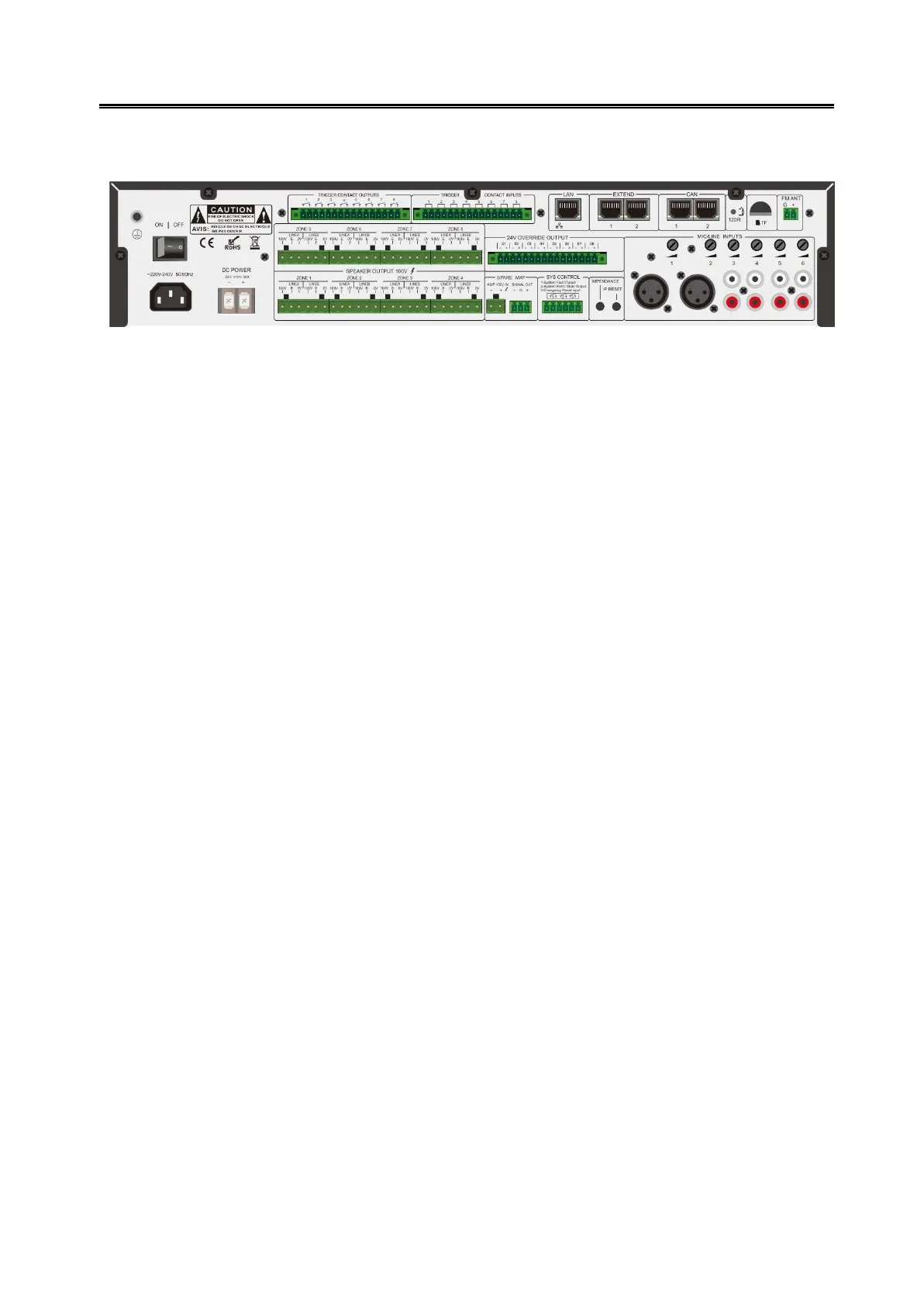
Figure 4- 2 VA-6200MA rear panel design sketch
ON for power on, OFF for power off.
AC power input socket.
DC POWER: 24V DC input interface, pay attention to positive and negative, Do
not reverse!
100V output interface, 24V relay control interface.
SPERKER OUTPUT 100V.
ZONE1 ~ 8
LINEA:zone A.
LINE B:zone B.
100V: loudspeaker positive.
E: relay interface.
0V: speaker negative.
TRIGGER CONTACT OUTPUTS: Short circuit signal output when fire alarm is triggered.
TRIGGER CONTACT ITPUTS: Fire trigger input interface.
24V OVERRIDE OUTPUT: DC24V output interface for 4-wired volumn control.
AMP 100V IN: standby power amplifier 100V input interface (note positive and
negative);
SIGANL OUT: signal output interface, access to the standby amplifier input port.
Note: When using the standby power amplifier, you need adjust its volume to the appropriate
position to ensure the amplifier is 100V output.
System Fault Output—When the system is running normally, the system fault output is
turned off; after the fault and power is cut off, the system fault output is turned on.
System EVAC Output—When fire alarm is triggered, this port will output a short circuit
signal.
Emergency Rest Input—when short-circuit signal is input, the fire alarm emergency
status will be reset.