Do you have a question about the ITech IT6722 and is the answer not in the manual?
Details the one-year warranty services for product materials and manufacturing.
Lists circumstances under which warranty service does not apply.
Explains symbols like Caution, Warning, and Note for safe operation.
Outlines general safety measures to be followed during instrument operation.
Specifies the required indoor and low condensation environments for use.
Explains CE and WEEE directive tags indicating product compliance.
Details the WEEE directive requirements for electronic equipment disposal.
Lists applicable European directives and conforming product standards.
Lists items that should be included in the package for the power supply.
Guides on selecting a well-ventilated and rational-sized space for installation.
Provides steps and drawings for installing the instrument on a 19-inch support.
Explains AC power input levels and how to connect the power cord correctly.
Introduces the IT6700 series DC power supplies and their features.
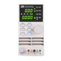
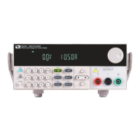
Identifies and describes the components on the front panel of the instrument.
Explains the function of various keys on the front panel.
Describes the meaning of characters and indicators shown on the VFD screen.
Identifies and describes the connectors and ports on the rear panel.
Explains the self-test procedure performed upon power-on.
Provides steps to verify voltage and current output functionality.
Explains how to switch between local and remote control modes.
Details the three methods for setting the output voltage from the front panel.
Details the three methods for setting the output current from the front panel.
Describes how to enable and disable the power supply output.
Explains how to switch the display between set and actual output values.
Discusses how voltage, current, and power limits affect output.
Describes how to save and recall frequently used parameter settings.
Explains how to use manual and BUS triggers for operation.
Details how to navigate and use the instrument's menu system.
Explains the Over Voltage Protection (OVP) feature and its operation.
Describes how to activate and deactivate the keypad lock function.
Explains how to use the remote sense feature to compensate voltage drop.
Lists key technical specifications such as rated values, load regulation, and accuracy.
Provides supplementary parameters like memory groups and calibration frequency.
Details the RS232 interface, data format, and connection.
Explains the USB interface functions for programming and control.
Describes the RS485 interface for multi-unit control and configuration.
Explains the GPIB interface connection and address setting.
Lists specifications for optional red and black test lines and current ratings.
| Model | IT6722 |
|---|---|
| Category | Power Supply |
| Power | 300 W |
| Voltage Resolution | 10 mV |
| Current Resolution | 1 mA |
| Operating Temperature | 0°C to 40°C |
| Weight | 6.5 kg |
| Humidity | ≤80% RH (non-condensing) |
| Cooling | Fan cooling |
| Input Voltage | 50/60 Hz |
| Output Current | 0-5 A |
| Current Accuracy | 0.1% + 5 mA |
| Line Regulation (CV) | 0.01% + 2 mV |
| Storage Temperature | -10°C to 70°C |