EasyManua.ls Logo

ITOH DENKI POWER MOLLER 24 HB-510N User Manual

ITOH DENKI POWER MOLLER 24 HB-510N
27 pages
To Next Page IconTo Next Page
Page #1 background imageLoading...
Page #1 background image
2 Great Valley Blvd., Wilkes-Barre, PA 18706
Office Ph: 570-820-8811
Fax: 570-820-8838
www.itohdenki.com
HB-510N/P
Designed to be functional with the FS and
FE series motors, as well as the higher
torque series FP
Run Hold timer added to the Forcible RUN
input
Now there is no need for an external
controller/timer with, or awkward
positioning of, a second sensor used for
infeeding the conveyor
Specifications subject to change without notice
Integral indexed rotary switch provides easy
speed adjustment without the need for
“tweaking”
More LED functionality to communicate
operating and error statuses
Selectable automatic or manual recovery for
thermal overload protection
Motor lock protection shuts motor down if it is
locked for at least 4 seconds
Lead free design for RoHS conformity
What's New:
Driver Card Manual
Features:
Logic for general zero pressure
accumulation (ZPA) control is built-in
Direct connection for a photo-sensor to
both power it and receive its output signal
Easy connection between adjacent HB-
510s with communication cables
simplifies wiring
Selectable singulated or slug (train)
release modes for ZPA function
Flexible Zone Recognition (patented) to
handle long articles which simultaneously
block multiple sensors
Only available in slug release mode
Synchronized speed variation to
simultaneously adjust the speed of the rollers
with a single external speed control signal
Stable speed function to ensure that different
weight articles travel at the same rate
As long as the load does not exceed the
rated torque for a given speed
Enclosure is made from fire resistant ABS
Question and Answer IconNeed help?

Do you have a question about the ITOH DENKI POWER MOLLER 24 HB-510N and is the answer not in the manual?

ITOH DENKI POWER MOLLER 24 HB-510N Specifications

General IconGeneral
BrandITOH DENKI
ModelPOWER MOLLER 24 HB-510N
CategoryDC Drives
LanguageEnglish

Summary

What's New

Key Features

Specifications Overview

Mechanical Dimensions

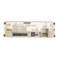
Provides physical measurements and dimensions of the HB-510 driver card.

User Interface and Default Settings

Details the default settings for DIP switches, rotary switch, and LEDs.

Standard Conveyor Configuration

Illustrates the standard setup for NPN output signal types in a conveyor system.

Electrical Connections

Connector Pin Assignments (CN1, CN2, CN3)

Details pinouts for CN1 (Power), CN2 (External Control), and CN3 (Sensor).

Wiring Instructions

Provides guidance for connecting wires to CN1, CN2, and CN3 connectors.

Communication Connections

Communication Port (CN4, CN5) Pinouts

Details pinouts for CN4 & CN5 communication ports and their functions.

Communication Cable Wiring

Explains the straight-through wiring pattern for communication cables.

Motor Connections

CN6 Motor Connector Details

Details the 9 or 10 PIN connector for motor connection and wire assignments.

Installation Precautions (Part 1)

Sensor, Cable, and System Restart Precautions

Covers sensor type, card connection limits, correct cable usage, and restart procedures.

Power On and System Operation Precautions

Details precautions for powering on the system and operating it safely.

Installation Precautions (Part 2)

Compatibility, Power, and Grounding

Addresses HB-508S compatibility, power supplies, voltage drop, and grounding.

Environmental, Electrical, and Over-Speeding

Covers environmental limits, electrical safety, and over-speeding risks.

Operation Modes and Settings

Signal Blocking Configuration

Configures signal transmission and reception between communication ports.

Input/Output Settings

DIP Switch Configuration for I/O

Details DIP switch settings for speed, direction, thermal recovery, and output types.

Input/Output Settings Explained

Detailed I/O Functionality

Explains settings for reset, output types, sensor/synchronous output, and forcible stop/run.

Timer Settings

DIP Switch Timer Configuration

Details DIP switch settings for Sensor, Run Hold, and Jam Timers.

Timer Functionality

Sensor, Run Hold, and Jam Timer Operation

Explains how Sensor, Run Hold, and Jam timers control motor operation in ZPA.

Other System Settings

Release Modes and Motor Direction Control

Configures release modes (ZP1/ZP2), last zone mode (ZB/ZE), and motor direction.

Speed Adjustment Methods

Integral Rotary Switch Speed Control

Details how the integral indexed rotary switch adjusts motor speed.

Input Signal Types

NPN/PNP Input Configuration

Explains factory presets and how to change NPN/PNP input types via internal DIP switches.

Status Monitoring

LED and Error Indication Meanings

Details the meaning of LED states and error codes for troubleshooting.

Conveyor Zone Configurations

Standard Zone Setup

Illustrates the standard configuration for a non-infeed/discharge conveyor zone.

Conveyor Zone Configurations - Infeed

Infeed Zone Setup Details

Details the configuration for an infeed zone using two photo-sensors.

Conveyor Zone Configurations - Discharge 1

Discharge 1 Zone Setup

Describes the setup for Discharge 1 zone with external control for discharging.

Conveyor Zone Configurations - Discharge 2

Discharge 2 Zone Setup

Details the setup for Discharge 2 zone with external control for accumulation.

Interconnecting Devices

Connecting to HB-508S: Option 1

Recommended method for connecting HB-510 to HB-508S via cable modification.

Interconnecting Devices: Option 2

HB-508S to HB-510 Connection (No Cable Mod)

Details connection and DIP switch settings for HB-508S to HB-510 without cable modification.

Interconnecting Devices: Option 3

HB-510 to HB-508S Connection (Partial Cable Mod)

Details connection and DIP switch settings for HB-510 to HB-508S with partial cable modification.

Driver/Slave Card Operation

Document Revisions

Related product manuals