NEW STRALIS MY2016 ‒ GUIDELINES FOR BODYBUILDERS
ELECTRONIC SUB-SYSTEMS
5.10 MISCELLANEOUS
51
– Printed 692.68.697 – 5 Ed. - Base 03/2019
Precautions
● Incorrect installation of electrical accessories may affect occupant safety and cause severe damage to the vehicle.
Contact IVECO if you have any questions.
● Avoid coupling with signal transmission cables (e.g. ABS), for which a preferential path has been defined for electromagnetic
requirements (EMI).
It should be noted that when grouping several cables together, in order to compensate for the lower heat dispersal capacity
current intensity must be reduced with respect to the nominal value of a single cable.
● In vehicles with frequent engine start-ups, with limited current drawn and engine rotations (e.g.vehicles with refrigeration
chambers), provide for periodic battery charging to maintain efficiency.
● Plug and terminal connections must be protected, resistant to weathering, and executed using components of the same type
as those utilised originally on the vehicle.
● In the event that a component has to be installed just next to the route of a cable belonging to the original system, make sure
that its remains integral and avoid any cuts.
▶ Any damage caused by failure to comply with procedure is not covered by warranty.
b) Interventions for modifying the wheelbase and overhang
Should it be necessary to lengthen the wires on the chassis owing to the new dimensions of wheelbase and overhang, a watertight
junction box must be used which has the same characteristics as those used on the standard vehicle. The electrical components
used such as wires, connectors, terminal blocks, conduits etc. must be of the same type as those used originally and must be cor-
rectly fitted.
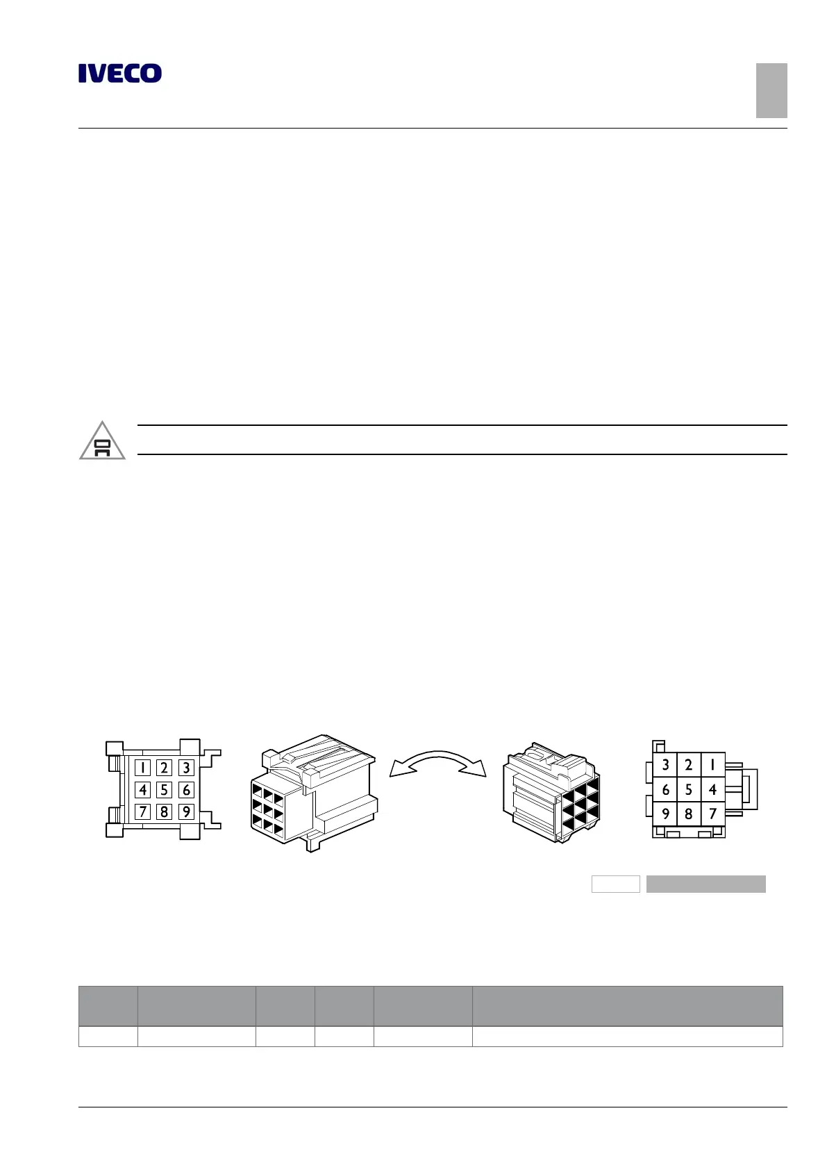
c) Connector ST14E
Connector ST14E may be present on New Stralis in the case of applications in which opt. 6821 (EN 1501) is fitted by the Service
Assistance after the vehicle has been purchased.
190412
Figure 38
OPT 6821 is incompatible with OPT 14861 (HillHolder)..
Please contact the IVECO Service Assistance to have the control units reprogrammed (EM, EBS, IC, ...).
Table 5.22 - Basic functions of connector ST14E
Pin Description
cable
code
Max.
Load
Connected to Remarks
1 Ground 0000 – EM X1-05
 Loading...