AYXP12JHRN
2 – 13
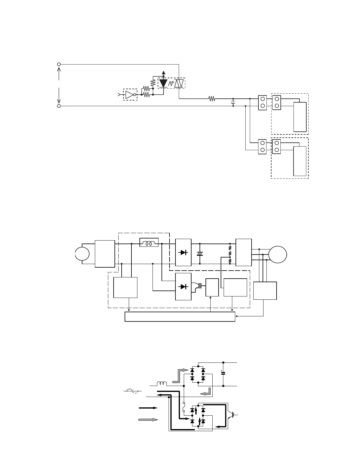
2. Explanation of cluster circuit
The cluster unit generates cluster ions, which are circulated throughout the room by the air flow created by the blower fan (indoor unit fan motor) in
the air conditioner unit.
1) When microcomputer output turns "H," the IC13 output changes to "Lo," turning ON the SSR1 and applying 100 V to the cluster unit for the gener-
ation of cluster ions (positive and negative ions).
3. Outline of PAM circuit
3.1. PAM (Pulse Amplitude Modulation)
The PAM circuit varies the compressor drive voltage and controls the rotation speed of the compressor.
The IGBT shown in the block diagram charges the energy (electromotive force) generated by the reactor to the electrolytic capacitor for the inverter
by turning ON and OFF.
When the IGBT is ON, an electric current flows to the IGBT via the reactor (L5) and diode bridge (DB2).
When the IGBT turns OFF, the energy stored while the IGBT was ON is charged to the voltage doubler capacitor via the diode bridge (DB1).
As such, by varying the ON/OFF duty of the IGBT, the output voltage is varied.
5
1
12V
SSR1
R16
R18
IC13
AC230V
Microcomputer output
4
1
Cluster unit
R19
R17
6
2
4
1
C5
PAM drive circuit block diagram
Reactor L5
[PAM drive circuit]
+
Microcomputer (IC1)
AC
230V
Compressor
Noise
filter
AC clock
detection
circuit
DB1
IPM
DB2
Compressor
position
detector
IGBT
drive
circuit
IGBT
Overvoltage
detection
circuit
Stored energy
Reactor
L5
DB1
DB2
IGBT
IGBT ON
IGBT OFF
 Loading...