Do you have a question about the IVT GS-XP12HR-N and is the answer not in the manual?
Detailed technical specifications for the air conditioner model.
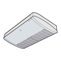
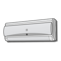
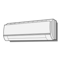
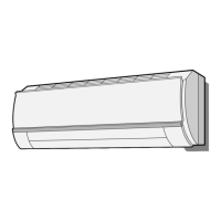
Physical dimensions and layout of indoor and outdoor units.
Specific measurements for installing the ceiling and floor type units.
List of electrical components used in indoor and outdoor units.
Schematic overview of the indoor and outdoor unit circuits.
Details of the electronic control system and circuit diagrams.
Explanation of various operating modes and control functions.
Guide to diagnosing and resolving malfunctions using self-diagnosis.
Diagram illustrating the refrigerant path through the system.
Specifies the standard operating conditions for testing.
Table showing temperature and pressure data at various points.
Graphs showing cooling and heating performance versus temperature.
Step-by-step instructions for disassembling the indoor unit.
| Brand | IVT |
|---|---|
| Model | GS-XP12HR-N |
| Category | Air Conditioner |
| Language | English |