EasyManua.ls Logo

IVT AE-X12FR-N User Manual

IVT AE-X12FR-N
41 pages
To Next Page IconTo Next Page
Page #1 background imageLoading...
Page #1 background image
CHAPTER 1. SPECIFICATION
[1] SPECIFICATION............................................ 1-1
[2] EXTERNAL DIMENSION............................... 1-2
[3] WIRING DIAGRM .......................................... 1-3
[4] ELECTRICAL PARTS .................................... 1-3
CHAPTER 2. EXPLAMATION OF CIRCUIT AND OP-
ERATION
[1] BLOCK DIAGRAMS....................................... 2-1
[2] MICROCOMPUTER CONTROL SYSTEM........ 2-3
[3] FUNCTION..................................................... 2-8
CHAPTER 3. FUNCTION AND OPERATION OF PRO-
TECTIVE PROCEDURES
[1] PROTECTION DEVICE FUNCTIONS AND
OPERATIONS................................................ 3-1
[2] AIR CONDITIONER OPERATION IN
THERMISTOR ERROR ................................. 3-3
[3] THERMISTOR TEMPERATURE CHAR-
ACTERISTICS...............................................3-5
[4] HOW TO OPERATE THE OUTDOOR
UNIT INDEPENDENTLY ...............................3-7
[5] GENERAL TROUBLESHOOTING CHART........3-7
[6] MALFUNCTION (PARTS) CHECK METH-
OD .................................................................3-9
[7] OUTDOOR UNIT CHECK METHOD........... 3-11
[8] TROUBLESHOOTING GUIDE ....................3-14
CHAPTER 4. REFRIGERATION CYCLE
[1] FLOW FOW REFRIGERANT ........................4-1
[2] STANDARD CONDITION ..............................4-1
[3] TEMPERATURE AT EACH PART AND
PRESSURE IN 3-WAY VALVE ......................4-1
[4] PERFORMANCE CURVES...........................4-2
AYXP12FRN
CONTENTS
Parts marked with " " are important for maintaining the safety of the set. Be sure to replace these parts with specified ones for maintaining the
safety and performance of the set.
This document has been published to be used for
after sales service only.
The contents are subject to change without notice.
TopPage
SERVICE MANUAL
SPLIT TYPE
ROOM AIR CONDITIONER
INDOOR UNIT
AY-XP12FR-N
OUTDOOR UNIT
AE-X12FR-N
MODELS
In the interests of user-safety (Required by safety regulations in some
countries) the set should be restored to its original condition and only
parts identical to those specified should be used.
Question and Answer IconNeed help?

Do you have a question about the IVT AE-X12FR-N and is the answer not in the manual?

IVT AE-X12FR-N Specifications

General IconGeneral
BrandIVT
ModelAE-X12FR-N
CategoryAir Conditioner
LanguageEnglish

Summary

CHAPTER 1. SPECIFICATION

[1] SPECIFICATION

Details technical specifications for indoor and outdoor units.

[2] EXTERNAL DIMENSION

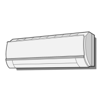
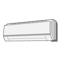
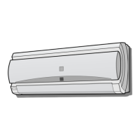
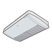
Provides physical dimensions for indoor and outdoor units.

[3] WIRING DIAGRM

Illustrates the electrical wiring diagram for the unit.

[4] ELECTRICAL PARTS

Lists and describes the electrical components used in the unit.

CHAPTER 2. EXPLAMATION OF CIRCUIT AND OPERATION

[1] BLOCK DIAGRAMS

Presents block diagrams explaining circuit operations.

[2] MICROCOMPUTER CONTROL SYSTEM

Details the microcomputer control system of the unit.

[3] FUNCTION

Explains various functions and operations of the air conditioner.

CHAPTER 3. FUNCTION AND OPERATION OF PROTECTIVE PROCEDURES

[1] PROTECTION DEVICE FUNCTIONS AND OPERATIONS

Describes the functions and operations of protective devices.

[2] AIR CONDITIONER OPERATION IN THERMISTOR ERROR

Explains unit operation during thermistor errors.

[3] THERMISTOR TEMPERATURE CHARACTERISTICS

Details thermistor temperature characteristics for indoor and outdoor units.

CHAPTER 4. REFRIGERATION CYCLE

[1] FLOW FOW REFRIGERANT

Illustrates the refrigerant flow path within the system.

[2] STANDARD CONDITION

Specifies standard operating conditions for testing.

[3] TEMPERATURE AT EACH PART AND PRESSURE IN 3-WAY VALVE

Lists temperature and pressure data for the 3-way valve.

[4] PERFORMANCE CURVES

Displays performance curves for cooling and heating capacities.

[4] HOW TO OPERATE THE OUTDOOR UNIT INDEPENDENTLY

1. Cooling in 40 Hz fixed mode

Details operating the outdoor unit independently in 40 Hz fixed mode.

[5] GENERAL TROUBLESHOOTING CHART

1. Indoor unit does not turn on

Provides troubleshooting steps for when the indoor unit does not power on.

2. Indoor unit fan does not operate

Offers troubleshooting for a non-operating indoor unit fan.

3. Indoor unit fan speed does not change

Guides on troubleshooting issues with indoor fan speed control.

4. Remote control signal is not received

Lists steps to diagnose and resolve issues with remote control signal reception.

[6] MALFUNCTION (PARTS) CHECK METHOD

1. Procedure for determining defective outdoor unit IPM/compressor

Outlines a procedure to identify faulty outdoor unit IPM or compressor.

[7] OUTDOOR UNIT CHECK METHOD

1. Checking procedures

Details inspection procedures for the outdoor unit after repairs.

[8] TROUBLESHOOTING GUIDE

1. Self-Diagnosis Function and Display Mode

Explains how to use the self-diagnosis function and interpret its displays.

Related product manuals