AYXP12FRN
2 – 14
4. Explanation of IPM drive circuit
The IPM for compressor drive is made by Mitsubishi Electric.
The power supply for the IPM drive, the shunt resistance for overcurrent detection, etc., are provided outside the IPM (control PCB).
4.1. IPM drive power supply circuit
The power supply for the upper-phase IGBT (HU, HV, HW) drive employs a bootstrap system, and provides power to the upper-phase IC.
The 15-V power supply for the lower-phase IC is provided by the control printed circuit board (PCB).
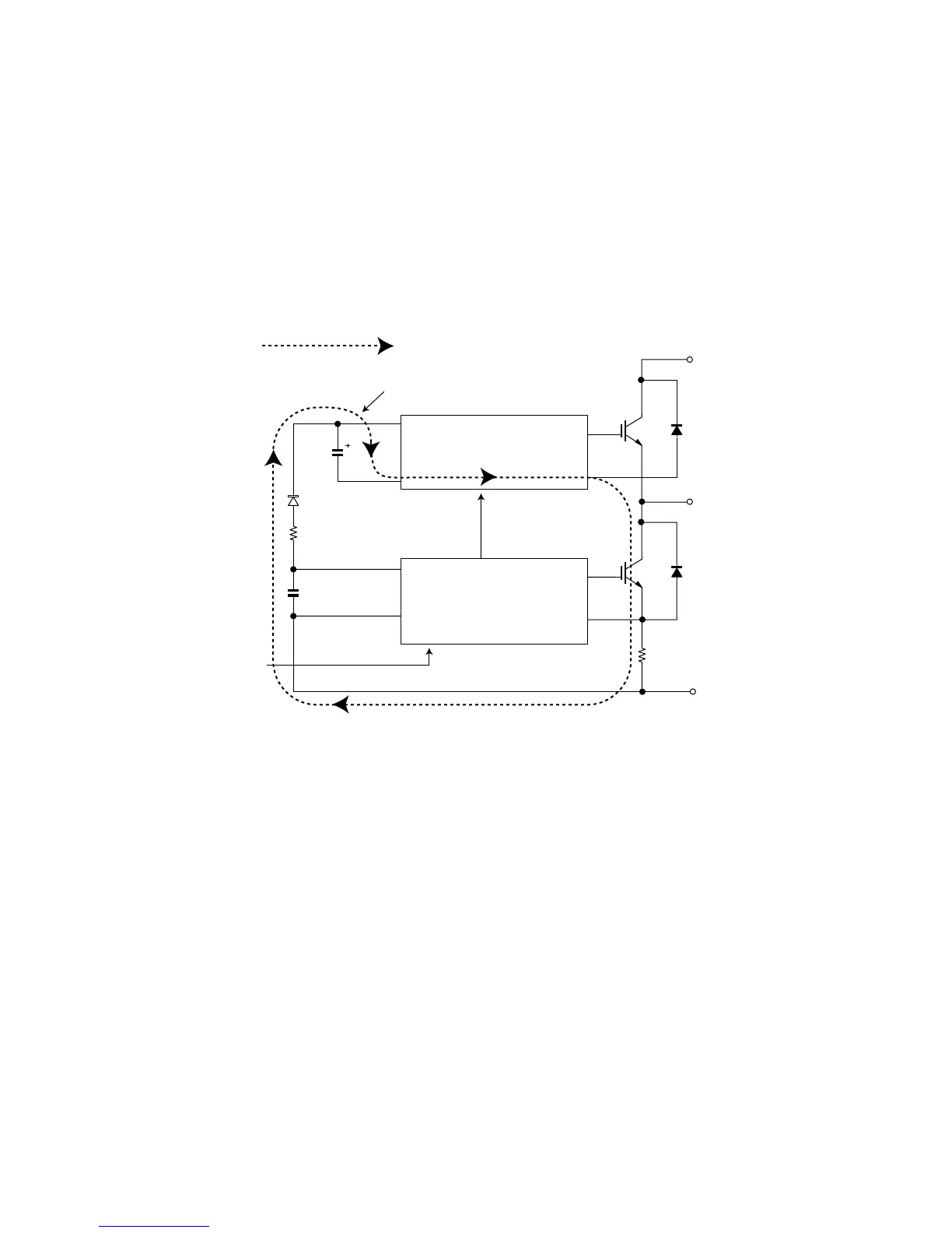
4.1.1 Brief explanation of bootstrap system (single power drive system)
To supply power to the upper-phase IC, the microcomputer (IC1) turns ON the lower-phase IGBT (LU, LV, LW).
This results in a charging current that flows to the electrolytic capacitor of each upper-phase IC input and charges the bootstrap capacitor with a 15-V
current.
The power supply for the subsequent stages is charged while the lower-phase IGBT is ON in ordinary compressor drive control.
P(Vcc)
U,V,W,
V
D
VDB
VCIN(n)
N-side
IGBT
N(GN
Bootstrap capacitor
High-voltage-withstanding,
high-speed recovery diode
LVIC
(LU,LV,LW)
HVIC
(HU,HV,HW)
Bootstra
circuit
Initial charge period
Charging current group
 Loading...