AYXP12FRN
2 – 15
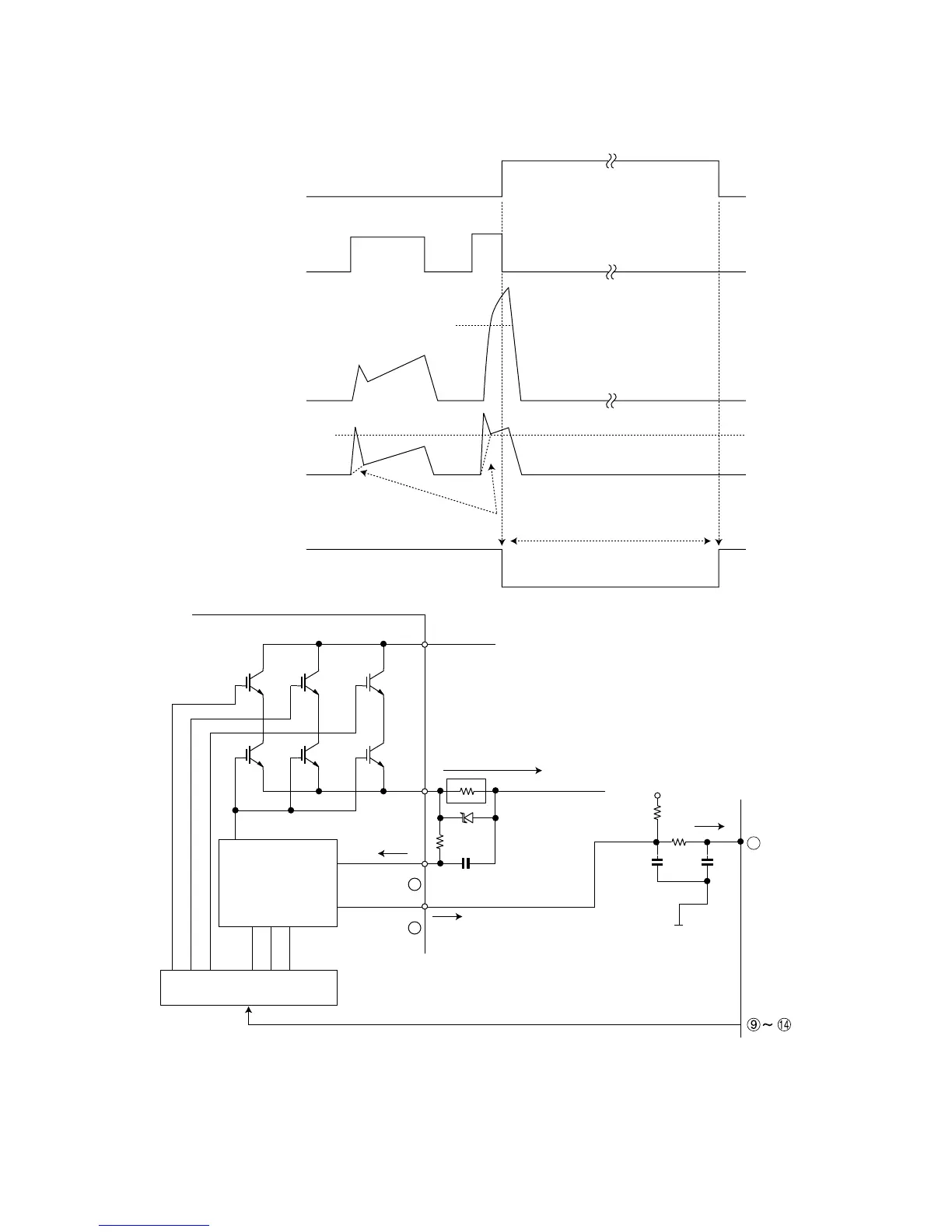
4.1.2 DC overcurrent detection circuit
When a current of about 25 A or higher flows through the shunt resistance (R49) on the control printed circuit board (PCB), the voltage at this resis-
tance is input to IPM CIN pin (26). Then, the gate voltage of the lower-phase IGBT (LU, LV, LW) inside the IPM turns OFF to cut off the overcurrent. At
the same time, an L output of about 1.8 ms is generated from IPM Fo pin (24), and this results in an L input to overcurrent detection input pin (34) of
the microcomputer (IC1) and turns OFF the PWM signal output (IC1 pins (51) through (56)) to the IGBT gate.
SET
RESET
(About 22 A)
SC
SC reference voltage
Delay by CR time constant circuit
About 1.8 ms
a1
Protection circuit status
Output current Ic (A)
Sense voltage relative
to shunt resistance
Error output Fo
(Lower phase)
Internal IGBT gate
IPM overcurrent
detection circuit
5V
0V
IC1
R49
Overcurrent
Shunt resistance
P
N
CiN
FO
24
26
34
 Loading...