AYXP12JHRN
2 – 14
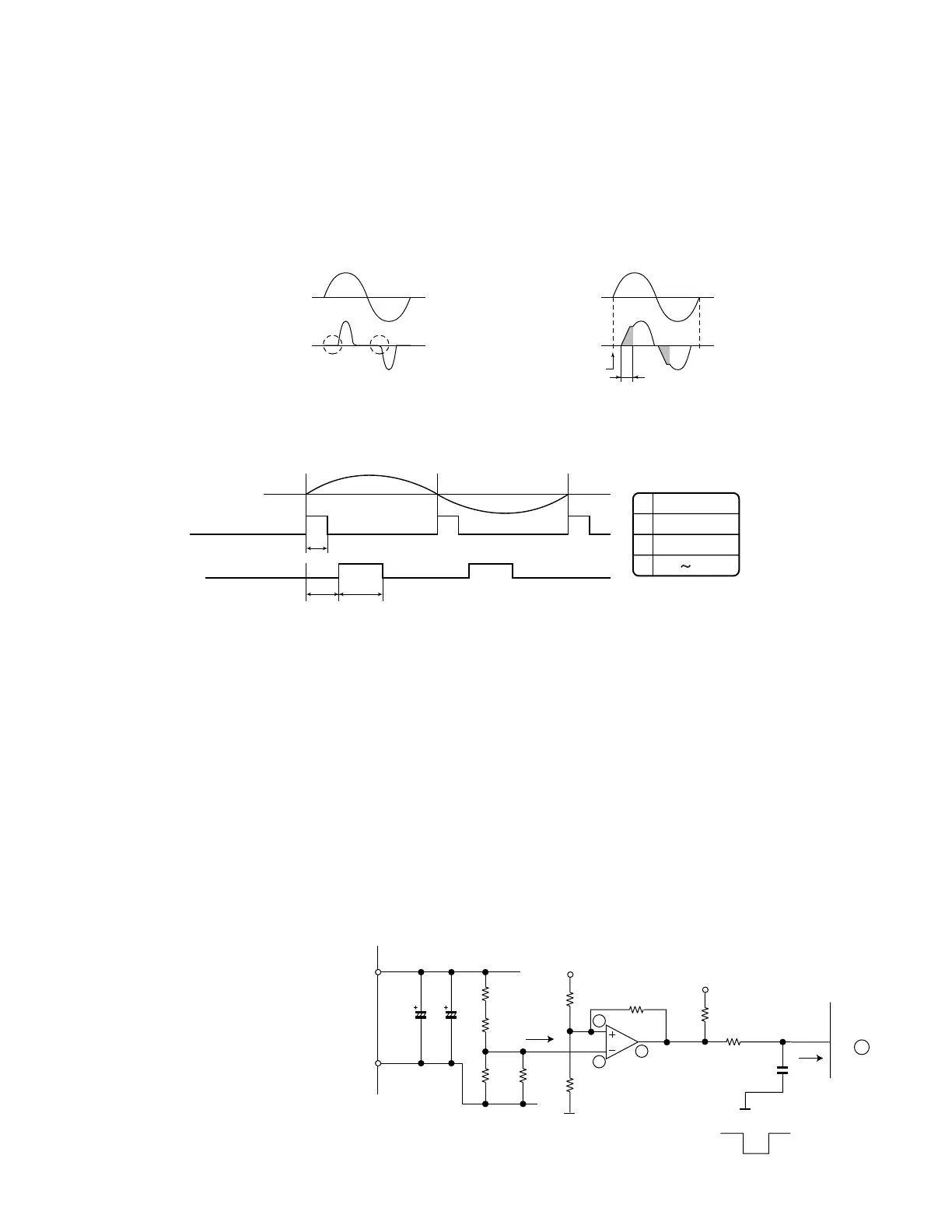
3.2. High power factor control circuit
This circuit brings the operating current waveform closer to the waveform of commercial power supply voltage to maintain a high power factor.
Because of the capacitor input, when the PAM circuit is OFF, the phase of the current waveform deviates from the voltage waveform as shown below.
To prevent this deviation, a current is supplied during the periods indicated by "O" in the diagram.
To determine the length of period to supply a current, the zero-cross timing of the AC input voltage is input to the microcomputer via the clock circuit.
The power source frequency is also determined at the same time.
The IGBT turns ON after the time length determined by the zero-cross point to supply a current to the IGBT via the reactor.
This brings the current waveform closer to the voltage waveform in phase.
As described above, the ON/OFF operation of the IGBT controls the increase/decrease of the compressor power supply voltage (DC voltage) to
improve the compressor efficiency and maintain a high power factor by keeping the current phase closer to that of the supply voltage.
3.2.1 Detailed explanation of PAM drive circuit sequence
3.2.2 AC clock (zero-cross) judgment
• The clock circuit determines the time from one rising point of the clock waveform to the next rising point.
The detected clock waveform is used to judge the power source frequency (50 Hz).
• The zero-cross of the AC voltage is judged as the rising of the clock waveform, as shown in the diagram above.
3.2.3 IGBT ON start time (delay time B)
• Based on the zero-cross of the AC voltage, the IGBT turns ON after a delay time set according to the power source frequency.
3.2.4 IGBT ON time (C)
• After the above delay time, the IGBT turns ON to supply a current to the reactor.
• The ON time of the IGBT determines the amount of energy (level of DC voltage rise) supplied to the reactor.
DC voltage level in each operation mode (varies depending on external load conditions)
– Cooling operation --- 260 to 280 V
– Heating operation --- 260 to 290 V
3.3. PAM protection circuit
To prevent excessive voltage of PAM output from
damaging the IPM and electrolytic capacitor as well
as the control printed circuit board (PCB), this circuit
monitors the PAM output voltage and turns off the
PAM control signal and PAM drive immediately
when an abnormal voltage output is generated. At
the same time, it shuts off the compressor operation.
The PAM output voltage is distributed to pin (4) of
the comparator (IC8). If this voltage exceeds the ref-
erence voltage at pin (5) of the IC8, the output of the
comparator (IC8) reverses (from H to L) and it is
input to pin (38) of the microcomputer (IC1) to halt
the PAM drive.
The protection voltage level is as follows.
AC voltage waveform
AC voltage and current waveform when PAM is ON
AC current waveform
IGBT ON period
Zero-cross detection
AC voltage waveform
AC current waveform
AC voltage and current waveforms when PAM is OFF
AC voltage waveform
Clock
IGBT ON
A
BC
A
B
C
50Hz
1.2mS
1.0mS
0.25 2.3mS
R2
255K
C10C9
420V
750uF
R5
300K
R7
23.7K
R8
23.7K
0V
0V
0V
IC8
15V
R113
19.1KF
R112
15K
R114
1M
5
4
2
(Overvoltage detection)
During abnormal voltage output
IC1
38
5V
R115
1.8K
R116
1K
 Loading...