Electric installation
AirModule 6 720 813 268(2014/10)
32
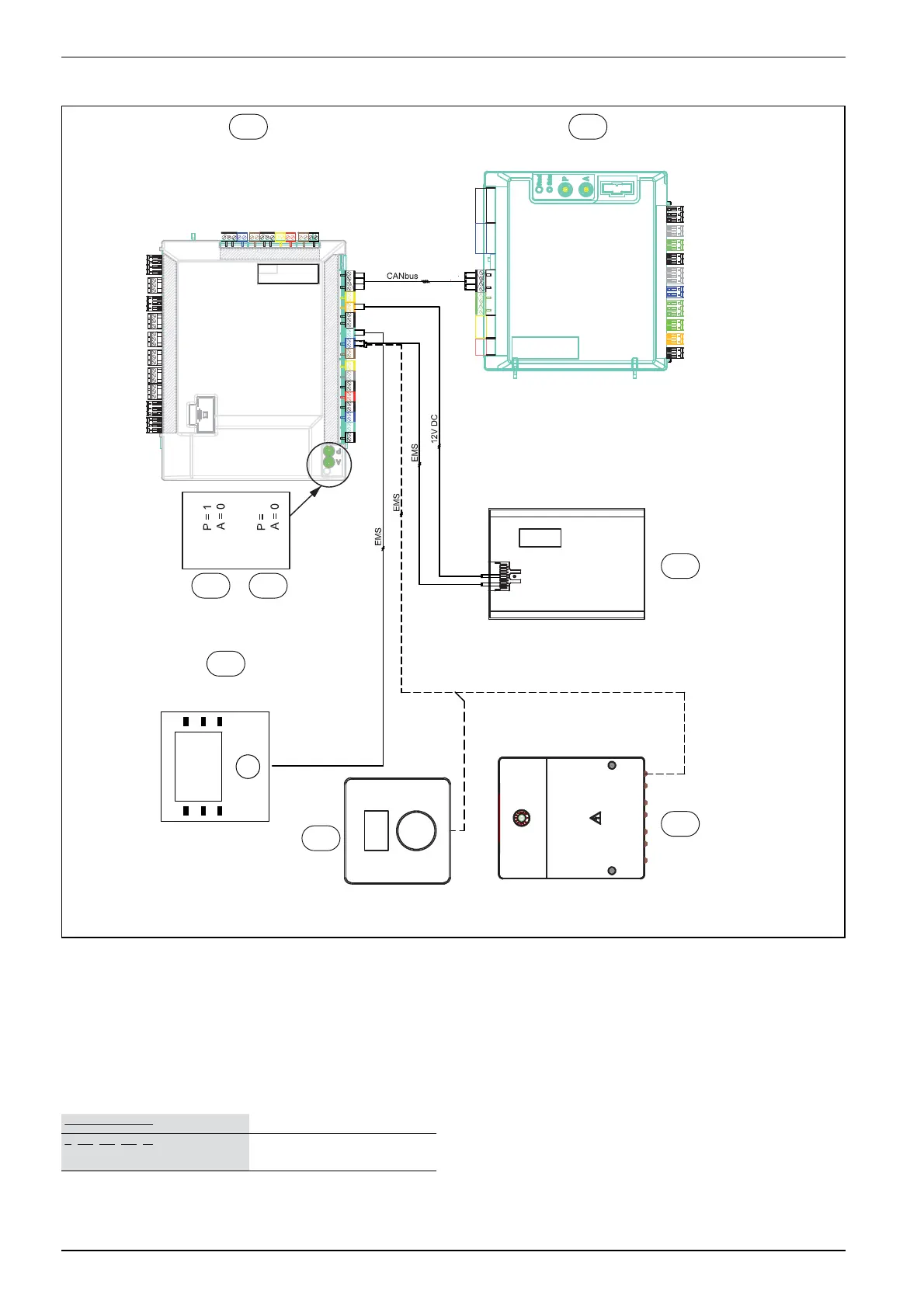
8.11 Heat pump/heat pump module circuit diagram
Fig. 32 Heat pump/heat pump module circuit diagram
[1] Heat pump module
[2] Heat pump
[3] IP module
[4] Accessories (extra heating circuit, pool, sun, etc.)
[5] Room controller (accessories)
[6] User interface
[7] Addressing with 9 kW immersion heater (standard setting)
[8] Addressing with 15 kW immersion heater (standard setting)
6 720 810 350-10.1I
1
6
4
3
2
87
2
9kW
15kW
5
Delivered connected
Connected during installation/
accessories
 Loading...