EasyManua.ls Logo

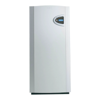
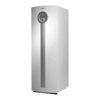
IVT Greenline E20 - User Manual

IVT Greenline E20
66 pages
To Next Page IconTo Next Page
Loading...
Guide to installation,
commissioning and maintenance
Greenline D14-D40
Greenline E14-E25
Article nr: 290430-9 Version: 4.0

Table of Contents

Question and Answer IconNeed help?

Do you have a question about the IVT Greenline E20 and is the answer not in the manual?

IVT Greenline E20 Specifications

General IconGeneral
BrandIVT
ModelGreenline E20
CategoryHeat Pump
LanguageEnglish

Summary

Control Panel Overview

Control Panel Buttons and Displays

Identifies and explains the function of each button and display element on the control panel.

Setting the Heating Curve

Troubleshooting Faults and Alarms

Alarm Examples and Remediation Steps

Explains common alarm messages and provides steps for self-remedy.

Control Panel Not Responding

Addresses issues where the control panel is unresponsive and suggests troubleshooting steps.

Comprehensive Alarm Guide

Compressor Motor Cutout Switch Alarm

Details the compressor motor cutout alarm, its causes, and reset procedure.

Heat Transfer Fluid Pump Switch Alarm

Explains the alarm for the heat transfer fluid pump, its causes, and how to reset it.

Pressure Switch Alarms

Low Pressure Switch Alarm

Describes the low-pressure switch alarm, its probable causes, and actions.

High Pressure Switch Alarm

Details the high-pressure switch alarm, its probable causes, and actions.

Specific Alarm Types and Resolutions

Compressor Superheat and Phase Sequence Alarms

Details compressor superheat and phase sequence fault alarms and their resolutions.

Power Failure and Electric Water Heater Alarms

Explains power failure alarms and electric water heater related issues and resets.

System Temperature and Sensor Alarms

High Return Temperature Alarm

Addresses the high return temperature alarm and steps to prevent it.

Heat Transfer Fluid System Max Alarm

Explains the alarm for maximum outgoing heat transfer fluid temperature and its causes.

Sensor Fault Alarm

Addresses general sensor faults, their causes, and troubleshooting steps.

Emergency Operation and Maintenance Procedures

Emergency Operation (E Series)

Explains how to operate the heat pump in emergency mode when normal operation fails.

Electrical and Heating System Integration

Electrical Connection Details

Details the electrical connections required for the heat pump and its components.

Connecting to the Heating System

Provides instructions on how to connect the heat pump to the heating system.

Circuit Diagram: Greenline D14-D16

Circuit Diagram: Greenline E14-E16

Circuit Diagram: Greenline D20-D40

Circuit Diagram: Greenline E20

Circuit Diagram: Greenline E25

External Connections: Greenline E Series

External Connections: Greenline D Series

Rego 600 Control Unit Overview

Installer;Service Settings Access

Describes access to advanced settings for installers and service personnel.

Installer;Service Menu Navigation

Explains how to navigate the installer/service menu for advanced configurations.

Heat Pump Commissioning Process

Menu Navigation for Commissioning

Explains how to navigate the menu structure to access specific settings for commissioning.

Commissioning Mode A (D and E Series)

Commissioning Mode B (D Series)

Commissioning Mode C (D Series)

Post-Commissioning Checks

Related product manuals