EasyManua.ls Logo

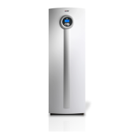
IVT Greenline HC 22 User Manual

IVT Greenline HC 22
112 pages
To Next Page IconTo Next Page
Page #1 background imageLoading...
Page #1 background image
Installation manual
Greenline HC
6 720 641 855-01.1I
HC 22 / HC 33
6 720 645 504 (2011/04) en

Table of Contents

Question and Answer IconNeed help?

Do you have a question about the IVT Greenline HC 22 and is the answer not in the manual?

IVT Greenline HC 22 Specifications

General IconGeneral
BrandIVT
ModelGreenline HC 22
CategoryHeat Pump
LanguageEnglish

Summary

Safety and Symbols

Understanding Warning Symbols and Safety Precautions

Explains hazard symbols and provides essential safety guidelines for installation and use.

Installation and Transport Tools

Lifting the Heat Pump

Correct Lifting Belt Attachment

Instructions for securely attaching lifting belts to the heat pump for safe lifting.

Product Details and Pre-Installation

Handling Electronic Components

ESD Protection for Circuit Boards

Procedures for safe handling of circuit boards to prevent electrostatic discharge damage.

Dimensions and Clearances

System Diagrams

System Configurations

System Schematics

Technical Specifications Overview

Installation Requirements

Collector and Heating System Installation

Covers installation, filling, and venting procedures for collector and heating systems.

Appliance Siting and Initial Setup

Sensor Installation and System Filling

Installing Temperature Sensors (T1, T2, T5)

Guidance on correct placement and installation of temperature sensors.

Filling Heating, Hot Water, and Collector Systems

Detailed steps for filling and venting various system circuits.

Collector System Filling Procedure

Electrical Connections

Connecting the Heat Pump and Phase Guard

Steps for connecting the heat pump electrically and understanding the phase guard.

Electrical Wiring Diagrams

Distribution Box to Heat Pump Connection Overview

Diagram showing the connection between the distribution box and the heat pump.

Electric Box Component Identification

External Connections

Wiring Diagram Explanations

Component Code Definitions (E11-E71)

Lists and defines component codes used in wiring diagrams for various system parts.

Internal Wiring Diagram

Overall Internal Wiring Schematic

A comprehensive schematic illustrating the internal wiring of the heat pump.

High Current Wiring Diagrams

Wiring Diagram E21 (High Current)

Detailed wiring diagram for compressor E21, focusing on high current connections.

High Current Wiring for Compressor E22

Wiring Diagram E22 (High Current)

Detailed wiring diagram for compressor E22, focusing on high current connections.

Low Current Wiring Diagrams

Wiring Diagram E21 (Low Current)

Detailed wiring diagram for compressor E21, focusing on low current connections.

Low Current Wiring for Compressor E22

Wiring Diagram E22 (Low Current)

Detailed wiring diagram for compressor E22, focusing on low current connections.

External Connections E21

Wiring Diagram for E21 External Connections

Illustrates the external connections to the E21 control unit.

External Connections E22

Wiring Diagram for E22 External Connections

Illustrates the external connections to the E22 control unit.

Additional Heat and Hot Water Heater Connections

Control Panel Overview and Operation

Identifying Control Panel Elements and Status Lamps

Identifies all buttons, the display, and status lamp indicators on the control panel.

Initial Start-Up Configuration

Setting Language, Country, and Operating Mode

Guides users through initial setup for language, country, and operating mode.

Key Start-up Parameter Adjustments

Details essential parameters to adjust during the initial start-up process for optimal operation.

Installer Menu Access and Sensor Information

Accessing Installer Level Functions

Procedure for accessing installer-specific menus using an access code.

Room Temperature Settings

Hot Water and Holiday Settings

Timer and External Control Settings

Additional Heat and Safety Functions

Collector Circuit Safety Settings

Defines safety limits and alarm parameters for the collector circuit's temperature.

Circuit 1 Heating Parameters

Heat Curve Settings and Flow Temperature Limits

Adjusting the Heat Curve

Guides on modifying heat curves for radiator and underfloor heating systems.

Heat Curve Adjustment Details

Modifying Heat Curve Points

Instructions for adjusting the left and right points of the heat curve.

Heat Curve Hysteresis and Time Factor

Room Temperature Influence and Programs

Room Temperature Program Configuration

Hot Water Production Settings

Hot Water Peak Day and Interval Settings

Determines the day of the week and interval for hot water peak operation.

Hot Water Program and Mode Settings

External Control Configurations

Screed Drying Functionality

Screed Drying Phases and Activation

Details the screed drying process phases and how to activate the function.

Screed Drying Program Settings

Additional Heat Configuration

Additional Heat General Settings

Sets start delay, energy supply cut-off behavior, and additional heat only mode.

Hot Water Electric Heater and Additional Heat Program

Safety Functions and General Settings

Collector Circuit Safety Temperature Limits

Defines minimum permitted temperatures and hysteresis for collector circuit sensors.

Alarm Indication and Control

Access Level and Factory Reset

Alarms Overview

Alarm Log and History Access

Provides access to the alarm log and saves historical alarm information.

Alarm Categories and Window Display

Understanding Alarm Categories (A-Z)

Classifies alarms by type and seriousness, detailing their impact on operation.

Specific Alarm Functions: Pressure and Temperature

Hot Gas Temperature and Pressure Alarms

Details alarms related to high hot gas temperature, low/high pressure, and collector circuit issues.

Compressor, Circuit, and Phase Protection Alarms

Motor Cut-out, Phase Error, and Sensor Fault Alarms

Covers alarms from motor cut-outs, phase errors, and sensor failures.

Flow, Heater, and Collector Alarms

Flow Temperature, Heater, and Collector Circuit Alarms

Describes alarms for high flow temperature, heater overheat, and collector circuit issues.

Sensor Failure and Short Circuit Alarms

Flow and Outdoor Sensor Alarms

Details alarms for flow and outdoor sensors indicating failure or short circuits.

Room and Heat Transfer Fluid Sensor Alarms

Room and Heat Transfer Fluid Sensor Issues

Covers alarms related to room and heat transfer fluid sensors (failure/short circuit).

Collector Circuit and High Temperature Alarms

Collector Circuit Sensor and High Flow Temperature Alarms

Describes alarms for collector circuit sensors and high flow temperature (T8).

Operational and Communication Alarms

Additional Heat, Screed Drying, and CANbus Alarms

Details alarms for additional heat, screed drying, and CANbus/I/O board communication.

System Operation and Version Alarms

Temporary Stops and Program Version Alarms

Covers alarms for temporary stops due to limits and program version mismatches.

Alarm Log and History

Alarm Log Information Details

Explains the content and display of the alarm log, including categories and text.

Factory Settings: Room Temperature

Factory Settings: Safety and Alarms

Function Check Procedures

Refrigerant Circuit and System Pressure Checks

Guides for checking the refrigerant circuit and setting system operating pressure.

Collector Circuit Filling Pressure Check

Procedure for checking and topping up the collector circuit filling pressure.

Operating Temperature Checks

Maintenance Procedures

Regular Function Checks and Filter Cleaning

Recommends function checks, cable inspection, and filter cleaning.

Commissioning Protocol: Installation Information

Recording Installation Details and Component Types

Fields for capturing installation data, serial numbers, and component types.

Commissioning: Electrical and Functional Checks

Electrical Connections and Start-Up Checks

Verifies electrical connections, supply voltage, and performs initial start-up procedures.

Sensor, Pump, and Signal Checks

Checks sensor connections, circulation pumps, external signals, and basic function tests.

Commissioning: System Operation and Handover

Checking Additional Heat, External Signals, and Temperatures

Verifies additional heat operation, external signals, and recorded operating temperatures.
Related product manuals