Electrical connections
6 720 645 504 (2011/04) en
46
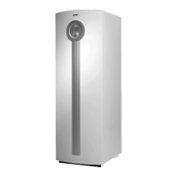
11.9 Connection of circulation pump
E41.E1.G1
Fig. 39 Connection of circulation pump E41.E1.G1
The circulation pump is part of the system solution with
mixed additional heat ( Chapter 8.2.3)
The circulation pump has its own voltage feed from the
distribution box. The pump is controlled from the
control unit. Incoming voltage feed is connected to
terminal block 72 and 74 on PHV1, outgoing voltage feed
on terminal block 73.
The maximum load is 2.6A when cos ϕ = 0.4. For
example, Wilo Star-Z 15 can be used.
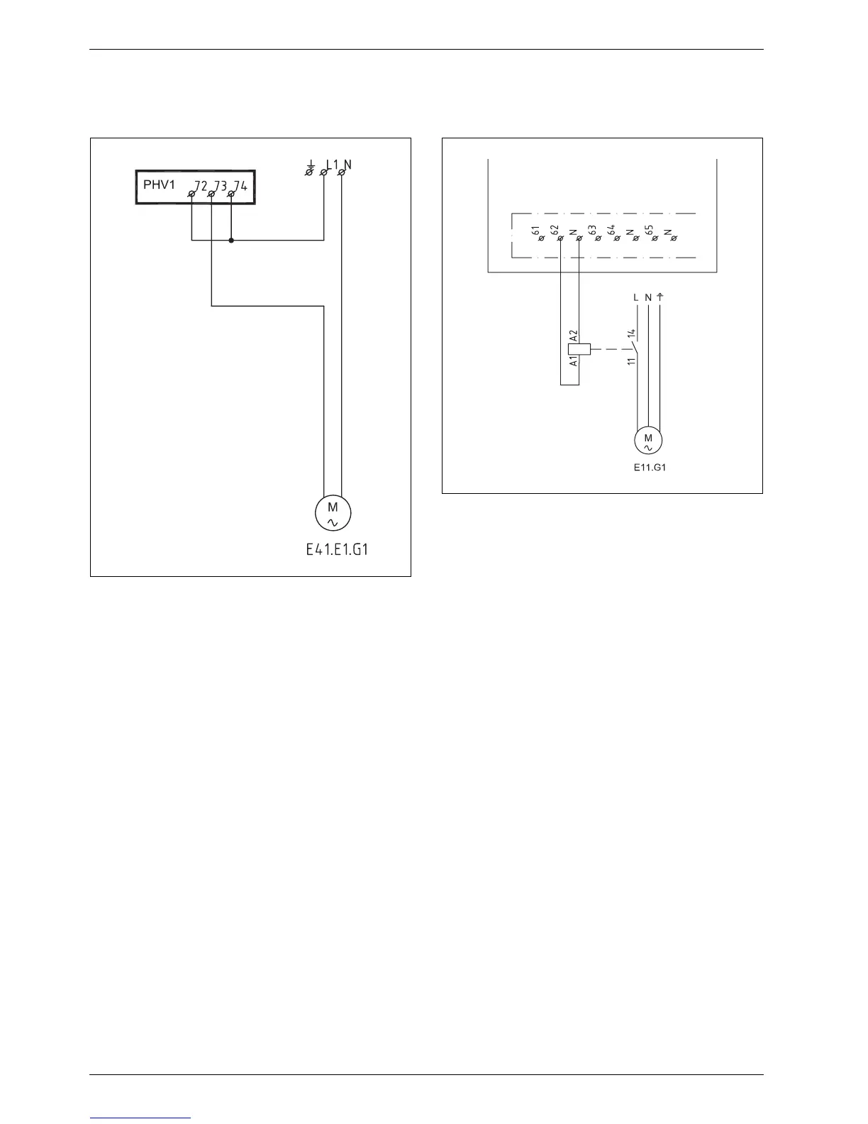
11.10 Connection of low energy pump
E11.G1
Fig. 40 Connection of low energy pump E11.G1
When a low energy circulation pump is connected in the
heating circuit an intermediate relay must be used for
pump control.
The relay is connected to terminal blocks 62 and N on
the PHV board (output for E11.G1).
E11.G1 is powered externally.
6 720 616 938-28.1I
6 720 645 810-01.1I
 Loading...


