Electrical connections
6 720 645 504 (2011/04) en
36
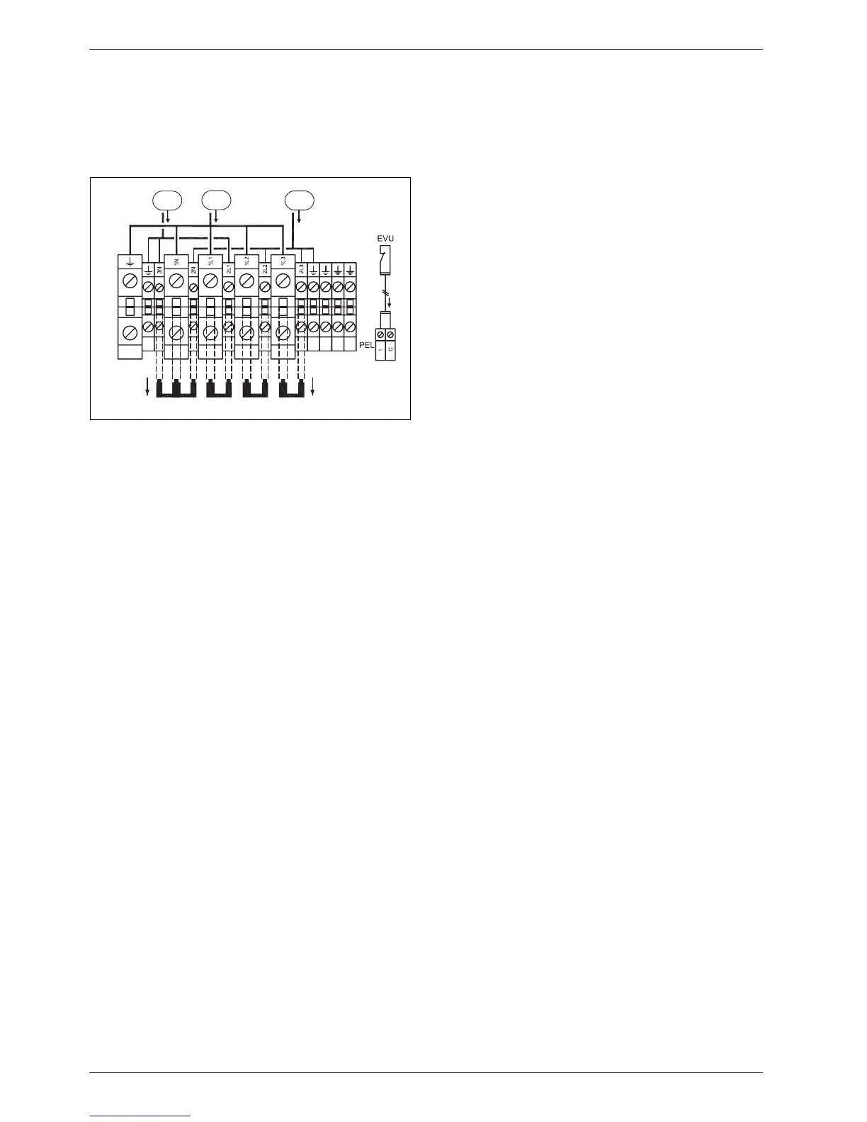
Alternative B
If the collector circuit pumps should be supplied
separately, they are connected to PE, 2N, 2L2 and 2L3.
Remove all terminal straps.
Fig. 29 Connection alternative B
1 Supply 1-phase L1 to control unit by EVU
2 Supply, heat pump
3 Supply, collector circuit pumps
11.5 External connections
All external connections are made on terminal board PEL
(low current) and PHV (high current):
B High and low current cables should be routed
separately in order to avoid interference on the
sensors (minimum distance of 100 mm).
B Use the following cable area when extending a
temperature sensor cable:
– Up to 20 m long cable: 0.75 to 1.50 mm
2
– Up to 30 m long cable: 1.0 to 1.50 mm
2
6 720 616 938-9.1I
2
3
1
 Loading...


