Installation
6 720 645 504 (2011/04) en
27
10.9 Temperature sensor installation
10.9.1 Flow sensor T1
B Operation mode without additional heat with buffer
tank. Install the sensor in the upper part of the tank.
See the installation manual for the buffer tank.
B Operation mode mixed additional heat (including
electric additional heat). Install the sensor in contact
with the flow pipe immediately after the mixing valve
(Q71) or after the additional electric heat.
10.9.2 Outdoor sensor T2
B Install the sensor on the coldest side of the house
(the north side). It must be protected from direct
sunlight, ventilation air or anything that can affect the
temperature measurement. The sensor must not be
installed directly beneath the roof.
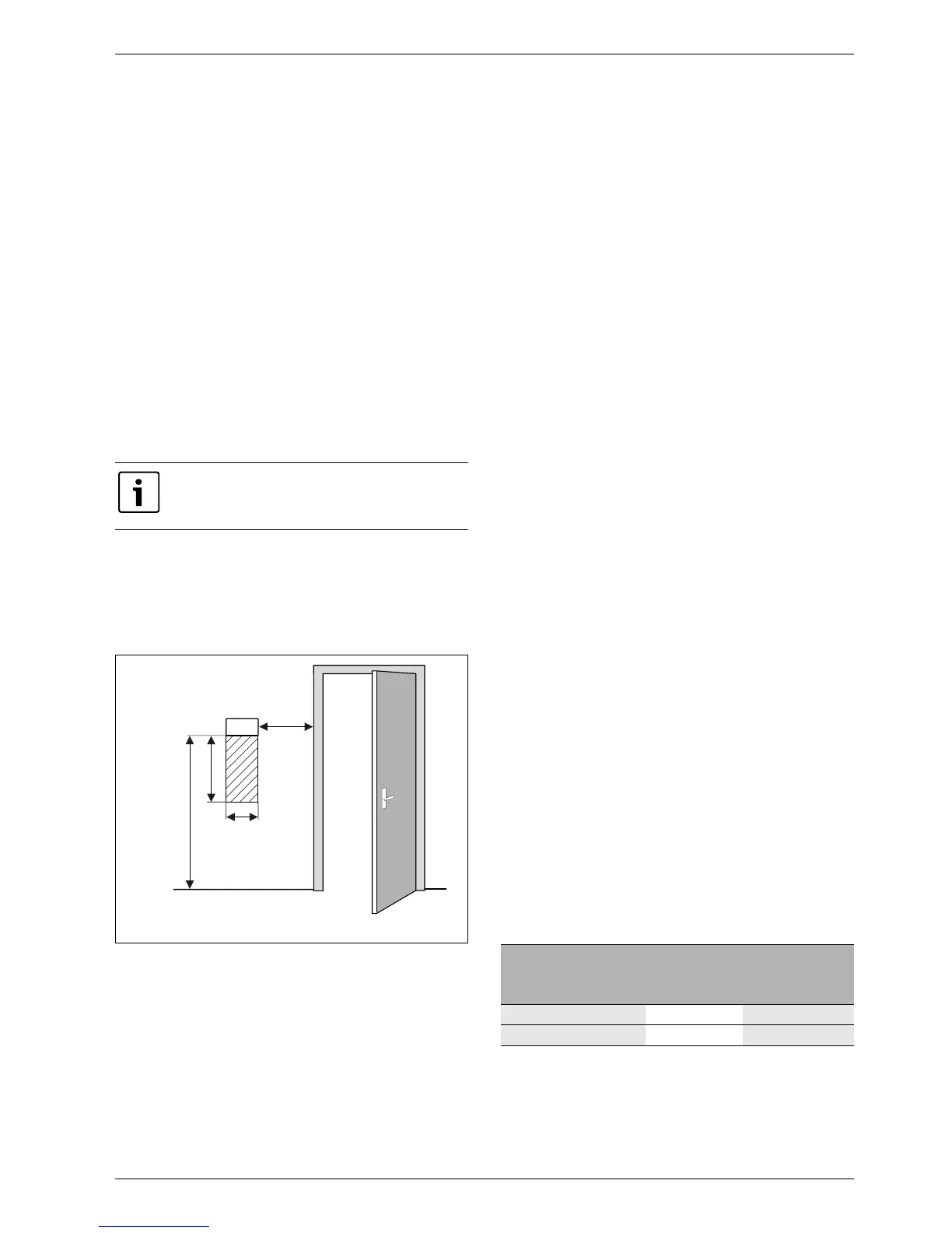
10.9.3 Room sensor T5 (accessory)
Installation location requirements:
• If possible, interior wall without drafts or heat
radiation.
• Unimpeded circulation of room air under room sensor
T5 (dotted area in figure 14 must be kept clear).
Fig. 14 Recommended installation location for room
sensor T5
10.10 Filling the heating system
B Open the heating system's valves.
B Open the tap on particle filter E22.V101 of the heating
system. Open valve E22.Q101.
B Fill up the heating system until the appropriate
pressure for the installation is reached. The maximum
permitted pressure is 4 bar.
B Vent the heating system.
B Drain some water out of buffer tank E11.C111 in
order to flush away possible particles from the tank.
Check and clean the particle filter if necessary.
B Check the pressure of the system and refill to the
appropriate pressure.
B Repeat the steps above if there is a lot of dirt in the
filter or tank.
B Check all connections for leaks.
10.11 Filling the hot water circuit
B Remove the cover of particle filter E21.V102. Position
the filter in an intermediate position.
B Position the 3-way valve E21.Q21 for heat production.
B Open shut-off valve E21.Q102 a bit and fill the circuit
carefully.
B Position the filter in operating mode and refit the
cover.
B Open the shut-off valve completely and perform
manual operation of the 3-way valve E21.Q21 in both
heating and hot water mode for venting.
B Check the pressure of the heating system and fill up,
if necessary, to a maximum of 4 bar.
B Check all connections for leaks.
10.12 Filling the collector system
The collector system is filled with collector circuit fluid
which must guarantee antifreeze protection down to
–15 °C. We recommend a mixture of water and glycol.
A rough estimate of the amount of collector circuit fluid
that is required in relation to the length of the collector
system and the inner diameter of the pipe can be made
using table 17.
It is only the room where the room sensor is
located that can influence regulation of the
temperature for the relevant heating circuit.
6 720 614 366-34.1I
0,3 m
0,3 m
0,6 m
1,2 - 1,5 m
T5
Inner diameter
Volume per metre
Single pipes
Double U
pipes
28 mm 0.62 l 2.48 l
35 mm 0.96 l 3.84 l
Tab. 17 Amount of collector circuit fluid
 Loading...


