This document provides a comprehensive fault tracing tree for the IVT X11-X15 heat pump series, designed to assist authorized service technicians in identifying and resolving operational issues. It emphasizes safety and systematic troubleshooting to ensure efficient and correct repairs.
General Function and Safety
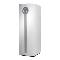
The IVT X11-X15 heat pump operates to provide heating and hot water, utilizing a cooling circuit and heat transfer fluid. The system is designed with various sensors and control mechanisms to monitor its performance and prevent damage. Safety is paramount, and all repairs must be carried out by authorized service technicians. Before any work, the main power switch and the power to the unit (via fuse or LS switch) must be turned off. Only original spare parts should be used for replacements. Customers are advised against modifying or repairing the installation and are recommended to have regular function checks performed.
Troubleshooting Process
The fault tracing process begins with a general assessment of the heat pump's status. Technicians should check all temperatures displayed in the main menu, manually operate all components to verify motor starts, and review all customer-adjustable settings, correcting them or resetting to factory defaults if necessary. The fault tables are structured for systematic use, guiding the technician from top to bottom and left to right. Each step involves a check, followed by a "yes" or "no" answer that directs to a specific action or the next troubleshooting stage. If a fault is rectified, the unit should start without an error message, completing the tracing. If the fault persists after actions and restarting, the technician proceeds to the next indicated stage. Any new faults discovered require consulting the relevant fault tables. It is crucial to note all present settings before starting and to restore them before leaving the appliance.
Display and Control Board Issues
Initial troubleshooting often involves the display and control board. If the display is out, checks include verifying if the miniature circuit-breaker (green fuse) has tripped, ensuring the transformer circuit board has 230V input and 12V output, and observing if the green LED on the control board is flashing. If the display LED is flashing, pressing the on/off button is the first action. Persistent issues may indicate a faulty display or a logic error in the control board, necessitating replacement. CANbus connections and terminations are also checked for communication issues between circuit boards.
Low Pressure Switch Tripping
A "Tripped low pressure switch" alarm indicates low pressure in the cooling circuit, requiring an acknowledgment on the display. The cooling circuit must be frost-protected down to at least -15 °C. Troubleshooting starts by checking if the heat pump has been stationary or recently commissioned. Manual operation of the HTF pump G3 is tested, verifying its start and operation at 30%. Voltage measurements on terminal blocks for G3 are performed. If the I/O circuit board does not transmit 3VDC, the glass fuse or I/O circuit board may need replacement. Wiring to the Stratos pump is checked, and if intact, the pump itself may be faulty. The green LED on the I/O circuit board is observed for flashing, and dirt filters on the cold side are inspected and cleaned. Ensuring sufficient fluid and addressing air in the collector circuit are also critical steps, potentially involving topping up with alcohol-mixed fluid or using a vent barrel. Finally, the LP switch's tripping value (1.5 bar) and its connection to Di1 are checked, with a faulty LP switch being a potential cause.
High Pressure Switch Tripping
A "Tripped high pressure switch" alarm signifies excessively high pressure in the cooling circuit, also requiring display acknowledgment. Manual operation of the compressor G2 is checked, along with voltage measurements on its terminal blocks. The response of G2 speed to relay HR1 activation is observed. The alarm history is consulted to understand the heat pump's state when the alarm occurred, particularly regarding the three-way valve. Dirt filters on the hot side are cleaned, and the flow in the heating circuit is assessed, ensuring thermostats are open. Air in the hot water heater is vented. Hot water settings are reviewed, and if temperatures are too high, they may need adjustment or resetting to default values. Sensor readings (T3, T8, T9) are compared with table values and external thermometer readings, with incorrect positioning or faulty sensors requiring replacement. The three-way valve's manual operation and stem movement are checked, potentially leading to motor or valve insert replacement. The HP switch's tripping value (31 bar) and its connections to Di3 and the I/O circuit board are verified. If the I/O circuit board's LED is not flashing, CANbus connections and power supply are checked. Ultimately, control logic errors may necessitate replacing the I/O circuit board, control board, or transformer circuit board.
High Hot Gas Temperature (T6)
An alarm for "High hot gas temperature T6" indicates the compressor temperature is too high. After acknowledging the alarm, the heat pump is started, and T6 temperature is monitored and compared with a digital thermometer. If values don't match, the T6 sensor attachment or the sensor itself may be faulty. Temperatures T10 and T11 are checked; if T10 is below -5 °C or the delta between T10 and T11 is 5°K or more, troubleshooting on the cold side is required. A refrigeration technician may need to inspect the cooling circuit, and in some cases, the expansion valve or compressor might need replacement due to overheating.
High Forward Flow (T1)
A "High forward flow T1" alarm indicates the forward flow temperature exceeds the set limit. The T1 temperature is checked and compared with an external thermometer. If values differ, the T1 sensor attachment or the sensor itself may be faulty. The heat pump is started in heating mode (60 Hz), and T8 and T9 temperatures are checked for a delta between 7-10°K. The dirt filter on the hot side is cleaned. The alarm history is reviewed to understand the heat pump's actions during the alarm, especially regarding hot water production. The three-way valve's manual operation and motor are checked, with potential replacement of the motor or valve insert. Temperature settings, particularly for T1, are adjusted if too high. Room sensor connection and settings (T2, T5) are verified, as high set point values can contribute to the issue. Logic errors may require replacing the control board or I/O card.
High Temperature Difference Heating System Water
This warning, "High temperature difference heating system water," indicates that the temperature difference between T8 and T9 is greater than a calculated value based on compressor frequency. The dirt filter on the hot side is cleaned. T8 and T9 temperatures are checked and compared with an external thermometer; if discrepancies exist, sensors may need replacement. The flow in the heating system is checked, ensuring thermostat valves are open. If the heating system is insufficiently sized, expanding the system volume (e.g., with a volume tank or more radiators) may be necessary.
Low Heat Transfer Fluid (Coll.) In (T10) and Out (T11)
"Heat transfer Fluid too low in T10" and "Heat transfer Fluid too low out T11" alarms indicate the collector fluid temperature is below set protection values. For T10, the incoming fluid temperature is below -8 °C, and for T11, the outgoing fluid temperature is below -10 °C. Both reset automatically when the temperature rises by 1K. Troubleshooting involves starting the heat transfer fluid pump in manual operation and comparing T10/T11 values with a digital thermometer. If values don't match, the respective sensor (T10 or T11) is replaced. For T10, if the value is not above -7 °C, the control board or I/O card may need replacement. For T11, a quick start of the compressor is performed, and the delta between 1 and 6K is checked. Low flow in the heat transfer fluid circuit is addressed by increasing pump speed, venting the circuit, cleaning the particle filter, and checking the fluid's freezing point. In both cases, insufficient energy in the heat absorbing system, especially in cold weather, can be a root cause.
Sensor Faults (T1-T3, T6-T11, T5, T81)
General sensor faults (open circuit, short-circuit) are common across various temperature sensors (T1-T3, T6-T11, T5, T81 for pool control). Display readings of -52.1 or 160 (or -60 for T5, 195 for T81) indicate a fault. The sensor is disconnected, and its resistance is measured and compared with a table. Wiring to the sensor is checked. Conductive pathways on the I/O circuit board (or pool circuit board for T81) are inspected for damage. CANbus connections between circuit boards are verified. If wiring is OK, the sensor or control board may be faulty. For T5, the room sensor tab in the control unit and its LED illumination are checked, along with CANbus wiring.
Electric Element Fault
An "Electric element fault" alarm indicates a reset on the overheat protection. The supply to the electrical additional heat (measured on the AHB circuit board terminals) is checked, along with wiring in the heat pump. Attempting to reset the overheat protection is the next step. If unsuccessful, the overheat protection electric element is defective, requiring replacement of the AHB board.
Compressor Frequency and HTF Pump G3 Faults
If the compressor does not reach the correct frequency (deviates by >5Hz for two minutes), the fault tracing tree for the inverter section (Chapter 2.4) is consulted, and the supply to the inverter circuit board is checked. A "Fault in HTF pump G3" alarm (Input Di4 low, delay 2 seconds) directs to the fault tracing tree for the heat transfer fluid pump G3 (Chapter 2.6).
High Temperature Electric Box
A "High temperature in electrical box" alarm indicates high temperature on the driver circuit board, measured by a sensor on the board. The fan in the electric box is checked for operation. If not running, output Do3 on the I/O circuit board is checked, and the fan or I/O circuit board may need replacement. Flow through the cooling coil is verified by checking if hoses to the electric box feel cold. If not, the heat transfer fluid circuit is opened and flushed, then properly vented. A defective thermistor in the driver circuit board requires replacement of the driver circuit board.
Connection Issues (AHB and I/O Circuit Board)
"Check connection to AHB board" and "Check connection to I/O circuit board" alarms indicate no contact with the respective boards. The green LED on the AHB or I/O circuit board is checked for flashing. In both cases, CANbus connections and terminations are verified. If these steps don't resolve the issue, the AHB board or I/O card may need replacement.
Inverter Section Troubleshooting
If the heat pump does not run, troubleshooting the inverter section involves a series of checks. This includes verifying 3x400V supply to the heat pump (L1-L2, L1-L3, L2-L3=400V) and checking the main fuse. The contactor connection is verified, allowing for a 9-minute time relay. Voltage measurements on the inverter circuit board (TBL1-TBL2, TBL2-TBL3, TBL3-TBL1=400V) are performed. Voltage between zero and miniature circuit breaker F3 (230V) is checked, as a tripped or blown F3 can be a cause. Voltage across glass fuse F1 on the transformer circuit board (PSU) and I/O circuit board (IOB) is measured (230V/phase to zero). Green LEDs on the I/O, AHB, and display circuit boards should flash (1/sec), and 12V on CANbus is checked. The red LED on the inverter circuit board should illuminate for a few seconds after the contactor connects. 15VDC voltage between terminal 5 and 7 on CN2 is verified. The choke coil connection to the inverter circuit board is checked against the wiring diagram. A ceramic power resistor connected to relay X52 on the inverter circuit board should have 16 ohm. Condenser connections to TB-P2, TB-C1, and TB-N1 are verified, and voltage between (TB-N1)--(TB-P2) (450-680VDC), (TB-N1)--(TB-C1) (225-340VDC), and (TB-C1)--(TB-P2) (225-340VDC) is measured. Wiring between the inverter circuit board and compressor is checked, and terminal block connections (TB-U to black, TB-V to brown, TB-W to grey) are verified. Voltage between (TB-U)--(TB-V), (TB-V)--(TB-W), and (TB-W)--(TB-U) is measured. If specific alarm codes appear in the rego window, separate fault tracing trees are consulted. Potential faulty components include the filter circuit board, contactor, glass fuse, inverter circuit board, wiring, or compressor.
Driver Circuit Board Alarms
The document lists various NAK codes for alarms from the driver circuit board.
- NAK 0-0 (Stoppage due to overheated heat sink): Check fan operation and contact paste between heat sink and electronics.
- NAK 0-1 (Stoppage due to overcurrent at start): Check inverter circuit board, compressor, and initiation data.
- NAK 0-2 (Stoppage due to overcurrent): Check inverter circuit board, compressor, and initiation data.
- NAK 0-3 (Stoppage due to overvoltage (DC)): Check 15V DC supply.
- NAK 0-4 (Current sensor warning): Current sensor defective, replace inverter circuit board.
- NAK 0-5 (Thermistor tripped on inverter circuit board): Faulty sensor in power transistor, replace inverter circuit board.
- NAK 0-6 (Current sensor tripped): Current sensor defective, replace inverter circuit board.
- NAK 0-7 (Data not received): Check 15V supply to inverter circuit board (13-18V on terminal block 5-7).
- NAK 0-8 (Stoppage due to undervoltage DC): Check 15V DC supply and condensers.
Heat Transfer Fluid (Coll.) Pump G3 Alarms
Error messages from the HTF pump G3 (E03, E10, E20, E21, E23, E25, E30, E31, E36) indicate various issues.
- E03 (Water temperature >110 °C): Heat regulation incorrectly set, set to lower temperature.
- E10 (Blocking pump): Often due to deposits. Unblocking procedure starts automatically; if it fails, contact service.
- E20 (Overtemperature winding): Motor overloaded, allow motor to cool, check filter and glycol content.
- E21 (Motor overloaded): Deposits in the pump, contact service.
- E23 (Short circuit/Earth fault): Defective motor, contact service.
- E25 (Contact fault): Module switched on incorrectly, switch module on again, check position and cleanliness of module and contact surfaces.
- E30 (Overtemperature module): Air supply to cooling body restricted, check for armaflex on heat sinks, ensure heat sinks are not blocked and air can pass.
- E31 (Overtemperature power section): Refer to E30.
- E36 (Defective module): Electronic components defective, replace module.
Warning Messages (G3 Pump)
Warning messages from the G3 pump (E03, E04, E05, E11, E38, E54) do not activate the SSM relay, and the pump continues to work. The cause must be rectified. If E04 and E05 persist for over 5 minutes in HW operating mode, they become error messages.
- E03 (Water temperature >110 °C): Heat regulation incorrectly set, set to lower temperature.
- E04 (Grid undervoltage): Grid overloaded, check electrical connections.
- E05 (Grid overvoltage): Incorrect supply from power company, measure voltage, contact power company.
- E11 (Idle pump): Air in pump housing, vent heat transfer fluid circuit.
- E38 (Temperature sensor medium defective): No specific action listed, implies sensor replacement.
- E54 (Connection I/O module): Connection interrupted, check that the 0-10V module is mounted in its base.
This detailed fault tracing tree provides a structured approach to diagnosing and resolving issues in the IVT X11-X15 heat pump, ensuring comprehensive and safe maintenance.