43
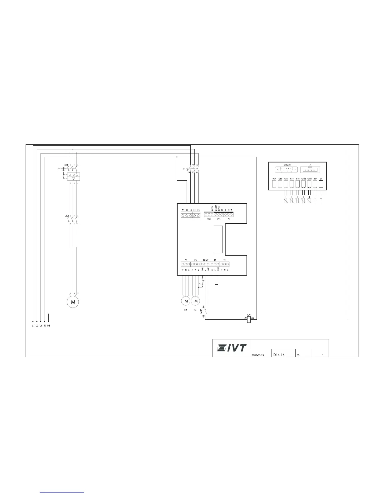
Sensor board
Internal couplings
Terminal card
Incoming supply
3 x400V + N + PE
Electric water heater 9 kW
(3 kW + 6 kW)
Low pressure switch
Pressure switch high
HTF (coll) out
HTF (coll) in
Heat trfr fld in
Heat trfr fld
Compressor
MB 1: Motor cutout compressor
CK 1: Contactor compressor
F1: Circuit-breaker heat pump
Compressor
Circuit diagram, Greenline D14-D16
* built-in motor cutout in the pump
CIRCUIT DIAGRAM
IVT GREENLINE D MODEL
DATE DRAWING NUMBER DRAWN BY PAGE