TR-800 EVALUATION KIT USER GUIDE V1.0
CONFIDENTIAL
All specifications are correct at the time of release. iWOW Connections owns the proprietary rights to the information contained herein this
document. It may not be edited, copied or circulated without prior written agreement by iWOW Connections Pte Ltd. iWOW Connections Pte Ltd
reserves the right to, at any time modify the document content without prior notice.
© 2005 iWOW Connections Pte Ltd
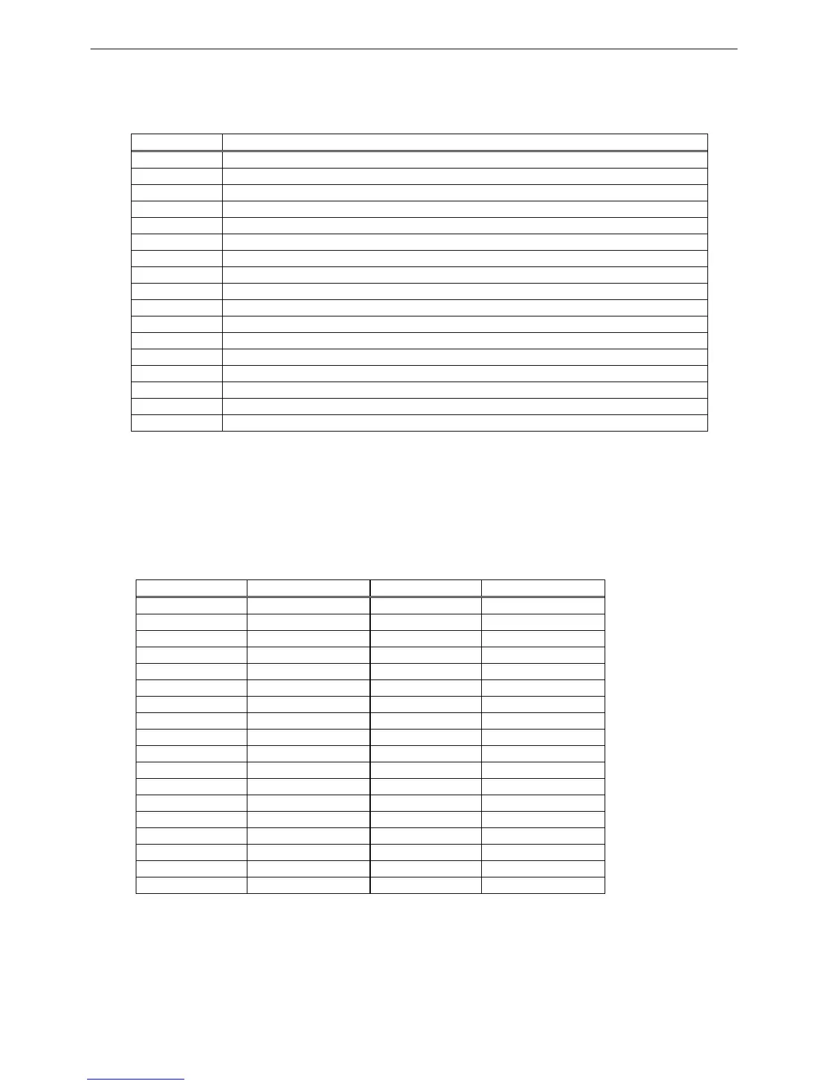
5.2 COMPONENT LIST
Reference Description
J1 80-pin connector – GSM/GPRS module
J2 DC supply jack
J3 External supply/battery input test points
J4 Backup battery connector
J5 SIM card holder
J6 Phone audio jack
J7 Auxiliary audio jack
J8 Modem Serial UART port
J9 Debug Serial UART port
J10 RF receptacle – for connection to module’s RF receptacle
J11 SMA jack – for RF connection to an external antenna or test equipment
SW1 RESET pushbutton
SW2 Power ON/OFF pushbutton
SW3 “CALL” function pushbutton
SW4 “1” function pushbutton
D1 LED indicator – MEB power supply
D2 LED indicator – Module status indicator
5.3 TEST POINT LIST
The test-points provided on the MEB allows access to module pins or features that are not
implemented or used on the MEB board itself, e.g. parallel bus, rest of keypad pins, battery
charging interface etc.
Test Point Function Test Point Function
TP86 D15 TP85 D14
TP84 D13 TP83 D12
TP82 D11 TP81 D10
TP80 D9 TP79 D8
TP78 D7 TP77 D6
TP76 D5 TP75 D4
TP74 D3 TP73 D2
TP72 D1 TP71 D0
TP70 CS3 TP69 CS2
TP68 /WR TP67 /RD
TP66 A4 TP65 A3
TP64 A2 TP63 A1
TP62 GND TP61 GND
TP60 CLK13M TP59 SCS0_SCL
TP58 SDI_SDA TP57 RST_OUT
TP56 KBR3 TP55 KBR4
TP54 KBR1 TP53 KBR2
TP52 KBC4 TP51 KBR0