FAA Approved Installation Manual for the Report No 908
EDM-900 and EDM-930 Page 27 of 56 Rev I
Primary Engine Data Management System Date 1-18-2013
1 and 2 again until the display (5 sec.) changes and you see FACTORY . At this point you will see MAIN = XX.,
adjust with the “Plus and Minus buttons. Tap next for AUX=XX and adjust. Tap button twice to finish and save.
26. GPS Interface
Use the J4 connector harness 790708 labeled RS232 OUT TO GPS (white) and RS232 IN FROM GPS (gray).
Refer to the Manufactures GPS manual for the required pin connections on the GPS.
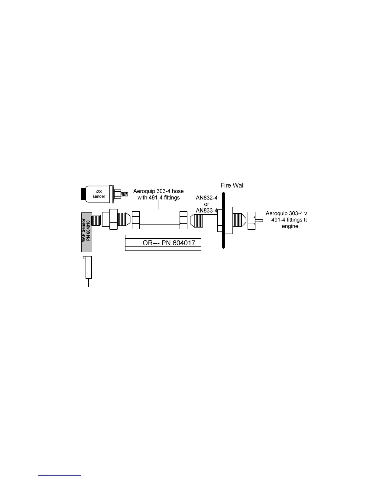
27. Manifold Pressure (MAP) Sensor
Screw a AN816-4D (flared to pipe thread) into the Aeroquip 303 hose to and from the bulkhead fitting an 832-4 as
shown below if not already installed from the aircraft factory MAP gauge.
27.1 Alternate method of Manifold pressure transmitter installation in aircraft using existing Manifold
Pressure gauge
For the JPI sensor use the J3 connector harness 790420 and connect the 4 leads using the supplied 4-pin
connector and pins.
Install a T-fitting in the aircraft’s MAP gauge line in the cockpit near the MAP gauge. Install the JPI MAP sensor P/N
604010 on the T-fitting. The MAP sensor uses a 1/8 NPT fitting.
 Loading...