Do you have a question about the J 133 and is the answer not in the manual?
Diagram illustrating deck hardware layout: winches, clutches, blocks, and lines.
Diagram showing J133 mainsheet and traveler system components and routing.
Diagram illustrating routing of main, jib/genoa, and spinnaker halyards.
Diagrams detailing the single line reef/Cunningham and second reef systems.
Diagram illustrating the J133 steering system components and their arrangement.
Diagram showing engine and exhaust system layout, including hoses and muffler.
Diagram illustrating J133 fuel system layout: tank, lines, and filter.
Diagrams showing the location of various thru-hull fittings on the J133.
Schematic of J133 fresh water system: pumps, faucets, tanks, and lines.
Schematic illustrating head and holding tank systems: pump-out and discharge.
Illustration of DC and AC electrical distribution panels and their components.
Top-view diagram showing layout of DC electrical components on the J133.
Schematic detailing standard DC wiring for J/133: panels, batteries, and connections.
Schematic for DC Link 2000 meter charging system: engine and battery connections.
Schematic of DC charging system: optional inverter and battery management.
Layout and schematic of AC main panel, shore power inlet, and outlets.
AC side schematic for optional inverter: breakers, bus bars, and connections.
Diagram showing LPG system layout: tank, regulator, solenoid valve, and stove.
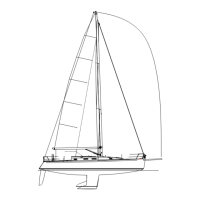
| Model | J 133 |
|---|---|
| LOA | 13.3 m |
| Water Capacity | 300 l |
| Engine | Yanmar 3JH5E |
| Berths | 6 |