2 / 8
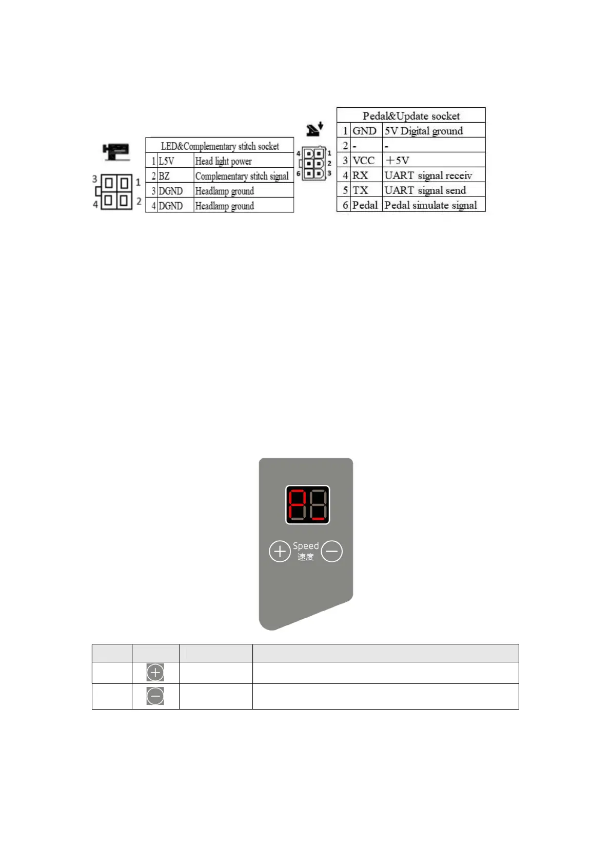
①Machine head button socket;②Pedal&update socket
Figure 1-2 Definition of control box socket
Note: if it cannot be inserted with normal force, please check whether the plug matches
the socket and whether the insertion direction or pin direction is correct!
1.3 Grounding and wiring
The grounding works of the system must be done well, and shall be constructed by
qualified electrical engineers. Before the product is powered on and put into use, it must be
ensured that the AC input end of the power socket has been safely and reliably grounded. The
grounding wire of the system is yellow green wire, which must be reliably connected to the
safety protection grounding of the power grid to ensure safe use and prevent abnormal
conditions.
Note: all power lines, signal lines, grounding wires and other wiring shall not be
pressed or excessively twisted by other objects to ensure safe use.
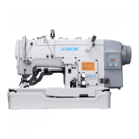
2. Display and operation interface
No. Icon Description Explanation
1
Up To quickly set the maximum speed and adjust parameters.
2
Down
To reset parameters, enter setting interface, quickly adjust
the maximum speed, etc.
3. Standby interface
In the standby interface, the first digit of the digital tube displays "P", and the
second digit of the digital tube displays the currently set needle stop positions. The