Page 2
OVERVIEW (FIG. 1 & 1-A)
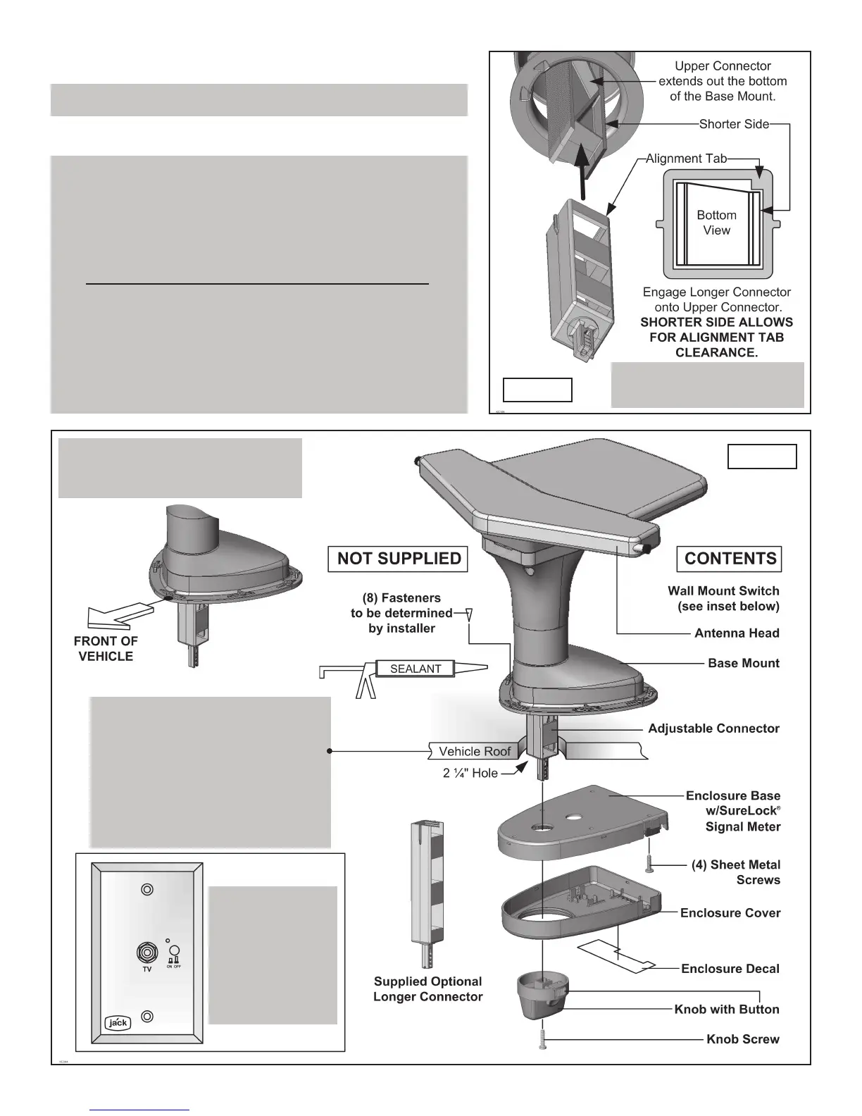
1. Verify contents and familiarize yourself with the parts (FIG. 1).
NOTE: Please read thru the instructions before beginning.
IMPORTANT!
For roofs 3 1/2” to 6” ONLY!
IMPORTANT!
The point of the base mount must
face towards the front of the vehicle.
IMPORTANT!
There are two lengths of adjustable
connectors included.
For roof thicknesses 1 1/4” to 3 1/2”
use the assembly as shipped.
For roof thicknesses 3 1/2” to 6”
use the longer connector.
IMPORTANT!
You must install
the included
wall mount switch
KC# PB1000
to operate the
JACK antenna.
(See page 5)
FIG. 1-A
FIG. 1
IF YOUR ROOF IS LESS THAN 3 1/2” THICK,
PROCEED TO THE NEXT PAGE.
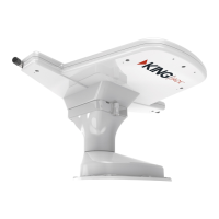
You only have to install the supplied longer connector for roofs
thicker than 3 1/2”.
If using the longer connector, install it now,
BEFORE INSTALLING BASE MOUNT ON ROOF (FIG. 1-A).
• Remove the existing adjustable connector from the upper
connector located in the base mount.
• Line up the tab with the shorter side as shown at right and engage
the longer connector onto the upper connector.
• Leave connector sticking out of base mount more than the
thickness of the roof.