59
A19 Troubleshooting The Optional Stereo System
The optional Stereo System provides a stereo receiver with high quality hot tub engineered speakers for supe-
rior sound quality. If the stereo deck does not turn on, refer to the following test procedure.
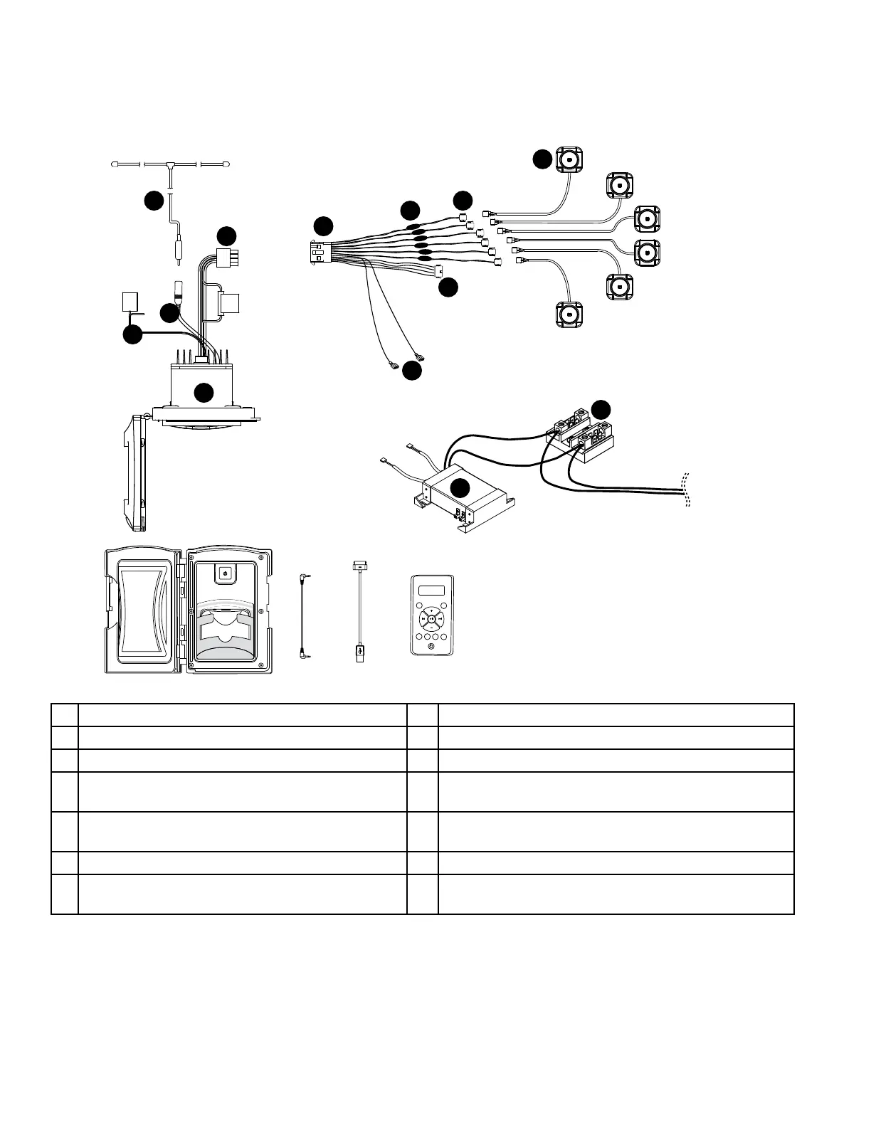
I. BLUEWAVE stereo diagram (follow the testing procedures for the Aquatic stereo)
E
J
M
L
K
H
D
A
F
G
USB connector
3.5 mm cable
30-pin
Connector
USB
AUX
AUDIO
MODE
REPEAT RANDOM
1
2
1
2
FM JET
DIR- DIR+
B
C
I
A BLUEWAVE stereo with connections H Spade connectors (connect to the power supply)
B Control Panel connection I Power supply (located in equipment bay)
C Antenna connection on stereo J TB1 terminal (located in control box)
D
Stereo harness (connects to wiring harness
“E”)
K Spa speakers (connect to wiring harness)
E
Spa wiring harness (connects spa compo-
nents to stereo)
L Stereo antenna
F Spa harness speaker connectors M Crossovers for the speakers
G
Subwoofer connector (connects to spa wiring
harness)
 Loading...