www.jacuzzi.com Page 3
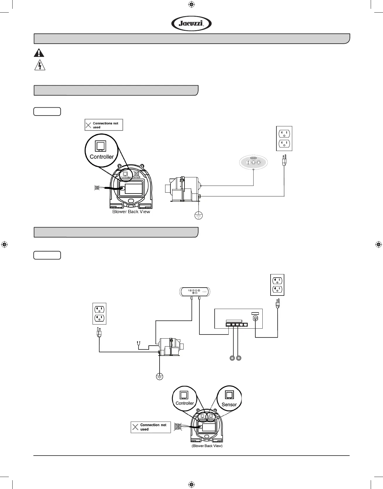
Reference Illustration for a Pure Air® System
These illustrations are for reference only, as the unit comes fully assembled.
DANGER: RISK OF ELECTRIC SHOCK! Before servicing these connections, disconnect all
power supply cables to both 120 VAC services.
J2 Control Panel Pure Air® Schematic Diagram
J4 Control Panel Pure Air® Schematic Diagram
Fig. 2
CONTROL
PANEL
BLOWER
120 VAC 15A
Dedicated GFCI
Circuit Required
G
Fig. 3
BLOWER
CONTROL PANEL
CHROMATHERAPY
LIGHTS 2X
Auto-Dri™
SENSOR
CABLE
LIGHT CONTROL
BOX
120 VAC
Panel
LED Light
120VAC 15A
Dedicated GFCI
Circuit Required
120VAC 15A
Dedicated GFCI
Circuit Required
 Loading...