www.jacuzzi.com Page 7
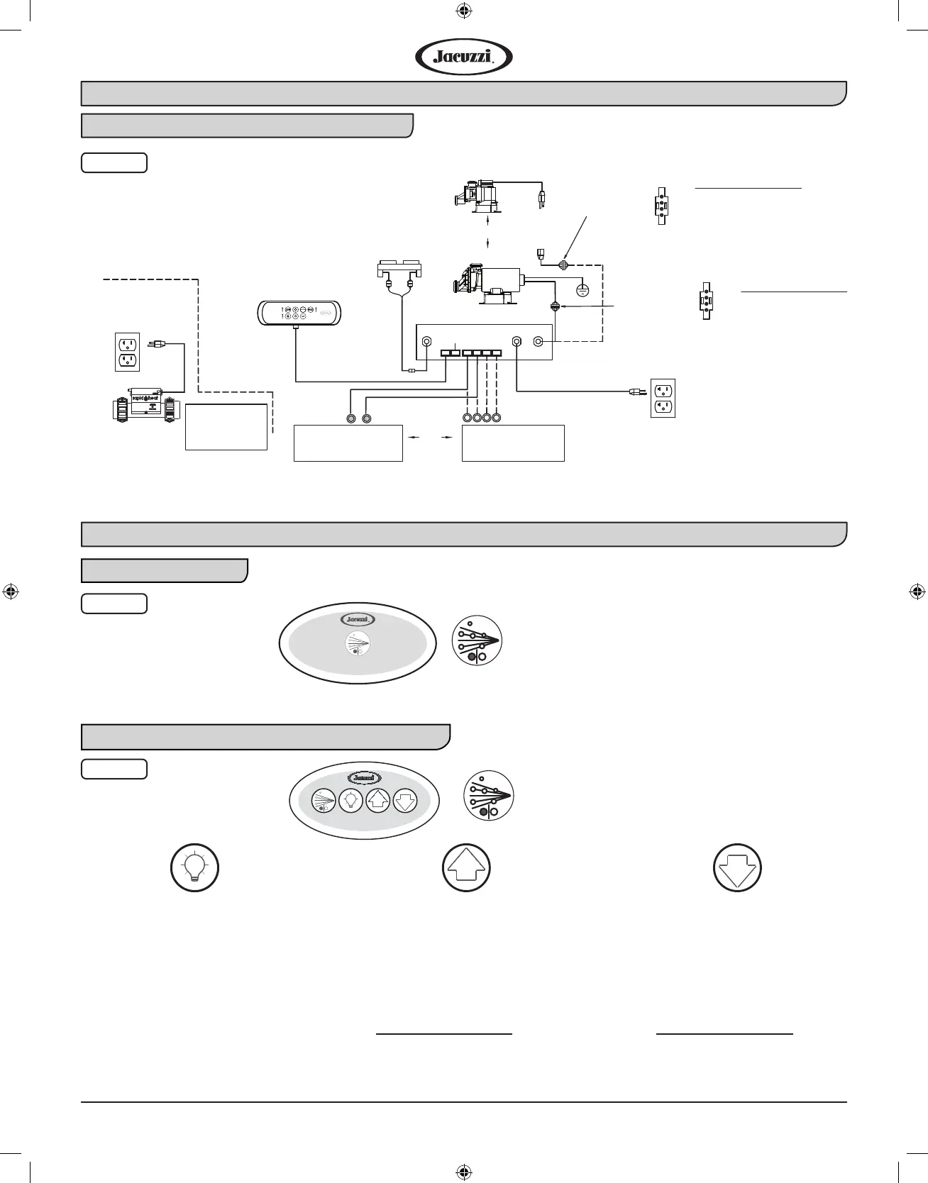
CONTROL PANEL
AIR VALVE
ASSEMBLY
CHROMATHERAPY
LIGHTS 2X
LEAD CONNECTIONS
4-WHITE-C
3-BLACK-H
2-N/A
1-GREEN-GRD
VIEW A
4-WHITE-C
3-BLACK-H
2-RED-L
1-GREEN-GRD
VIEW B
CONTROL BOX
120VAC
Pump
Panel
Blower
LED Light
PUMP/MOTOR
ILLUMATHERAPY
LIGHTS 4X
OR
120VAC 15A
Dedicated GFCI
Circuit Required
120VAC 20A
Dedicated GFCI
Circuit Required
SEE VIEW B
SEE VIEW A
OR
PUMP/MOTOR
Air Valve
FOR MODELS
WITH IN-LINE
HEATER
Fig. 8
Reference Illustration for a Whirlpool System (Continued)
Fig. 9
G
J2 Whirlpool Controls
J2 Whirlpool Controls with Chromatherapy Controls
Fig. 10
J4 Control Panel Whirlpool Schematic Diagram
Whirlpool Operations
• Press once to activate color
lighting.
• Press a second time to activate
solid White color.
• Press a third time to turn OFF.
NOTE: The Up and Down buttons
can be used to select colors or
intensity.
• Press button to activate the
color blending feature.
• Light sequence is as follows:
Blue, Teal, Green, Yellow, Or-
ange, Red, Pink, Purple.
• To select a solid color press
the Up button when the color is
displayed.
• Solid White color only: pressing
will increase the light intensity
NOTE: Default lighting color is solid
Blue.
• Press button to activate the
color blending feature.
• Light sequence is as follows:
Purple, Pink, Red, Orange,
Yellow, Green, Teal, Blue.
• To select a solid color press
the Down button when the
color is displayed.
• Solid White color only: press-
ing will decrease the light
intensity
NOTE: Default lighting color is
solid Blue.
G
• Press once to turn ON.
• Press again to turn OFF.
• Press once to turn ON.
• Press again to turn OFF.
 Loading...