14
JAGA NV | ROOM THERMOSTAT JRT | MANUAL | JANUARI , : | V..
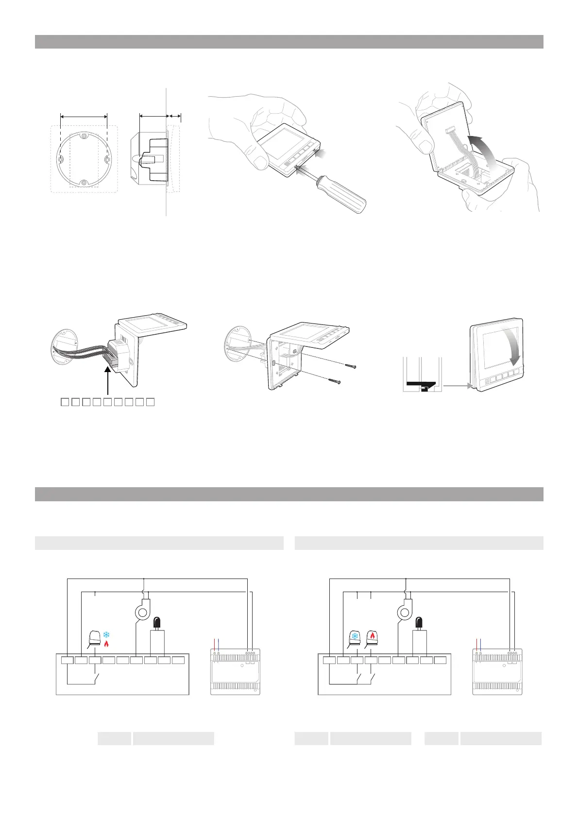
INSTALLATION
CONNECTION DIAGRAM
2PIPE CONNECTION 4PIPE CONNECTION
Important info : Make sure the electrical supply system complies with current National safety regulations.
Always use the main disconnect switch to isolate the unit from the mains before carrying out any maintenance or inspection work.
Mount a flush mounting box with screw holes at a mm
distance from the center.
Connect the device electrically.
Carefully remove the front panel
Attach the thermostat to the flush-mounted box with two
screws. Do not over tighten.
Carefully turn the front panel away from the rear panel.
Put the front panel back in place
H Heating C Cooling H/C Heating / Cooling
1.54.6
6
987654321
123456789
0...10V
SENSOR
COM
24V DC
C VALVE
H VALVE
L
+-
N
230 VAC
L1 N
+
-
123456789
0...10V
SENSOR
COM
24V DC
H/C VALVE
L
+-
N
230 VAC
L1 N
+
-
 Loading...