Installation 6-8
Revision 2 - 20 March, 1997 HP SERIES DIMMER OPERATING MANUAL
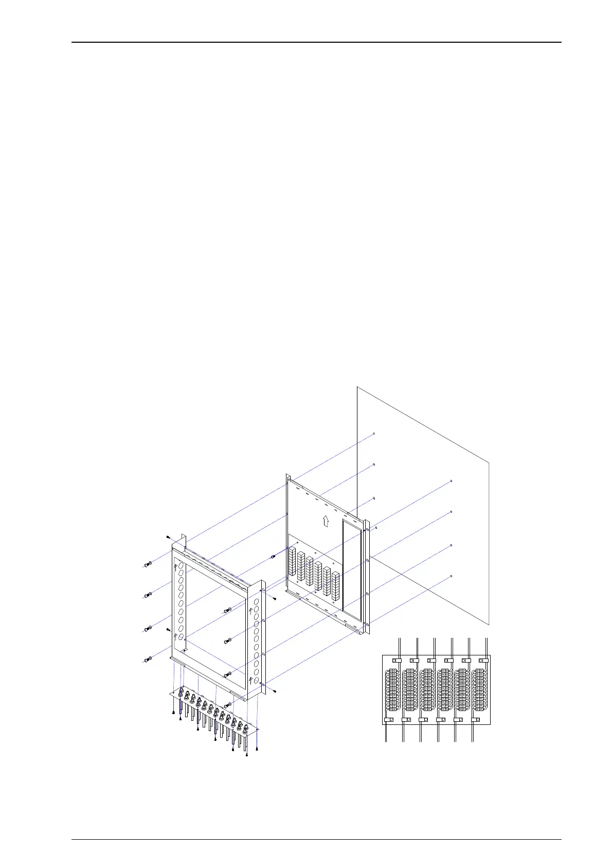
6.2.6 Wall Mounting Dimmers - Patch Lead Option
The wall-mount bracket system may include flying lead output patching. Two types of
flying lead patch options are available:
• Twenty four 3-pin Australian GPO plugs
• Twenty four 3-pin Wieland ST18 plugs
Output cables to the building are terminated at screw terminal blocks (with up to
4mm
2
capacity). These terminal blocks are supplied pre-wired to plugs on flying patch
leads, and may then be patched to any desired dimmer outlet socket.
To install:
1 Remove the bottom blanking plate from the deep bracket (eight screws).
2 Replace this with the pre-wired patch gland plate (use the same screws).
3 Fasten the deep bracket to the shallow bracket (see section 6.2.4).
4 Screw the terminal block plate to the shallow bracket (six screws).
5 Secure the whole assembly to the wall.
6 Connect the load wires to the terminal blocks.
7 Mount the dimmer (see section 6.3) and connect the supply and DMX cables.
WALL
TOP
1-4 5-8 9-12 13-16 17-20 21-24
OUTPUT CABLES
PATCH CABLES
 Loading...