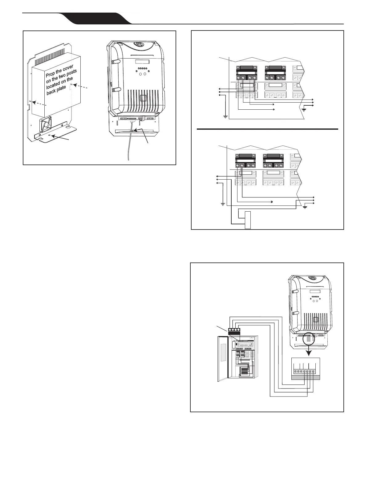
Figure 10. Wiring Power Pack to an AquaLink RS
or PDA Power Center (240 VAC and 120
VAC)
AquaLink RS or PDA Power Center
Filter Pump Relay
Aux.3Relay
Load
1
Line 1
120 VAC
To Filter Pump
(120 VAC)
To Power Pack
(120 VAC)
Neutral
To Breaker
Panel
Filter Pump Relay
Aux.3Relay
Load 2
Line 2
Load 1
Line 1
240 VAC
To Filter Pump
(240 VAC)
To Power Pack
(240 VAC)
To Breaker
Panel
Jandy
Power Center
Power Pack
OPTIONAL
4321
RED
BLK
YEL
GRN
Red, 4-Pin
Terminal Bar
RED
GRN
YEL
BLK
B
A
0V
POS
RED
BLK
Figure 11. Communication Wiring between Power
Pack and AquaLink
®
RS Control System
or PDA Network
Figure 9. Accessing and Wiring to the Power PCB
7. In the AquaLink
RS or PDA power center, wire the
power pack directly to the LOAD SIDE of the lter
pump relay
(see Figure 10 and 12).
8. The AquaLink
RS or PDA and power pack
use a
four (4) wire connection to communicate and can be
wired up to 500 feet apart. Any outdoor rated four
conductor cable, minimum 22 AWG, can be used.
Locate the appropriate screw terminals on the circuit
board and wire the power pack
to the AquaLink
RS
or PDA red 4-pin terminal bar
(see Figure 11).
NOTE The screw terminals on the AquaLink RS or
PDA are removable to aid in installation.
Page 6
Jandy
®
Pro Series AquaPure
®
Ei™ Series
|
Replacement Kit Instructions

 Loading...