Do you have a question about the Janome MC8900 QCP and is the answer not in the manual?
Procedure to remove and attach the face cover.
Procedure to remove and attach the top cover.
Procedure to remove and attach the belt cover.
Procedure to remove and attach the machine base.
Procedure to remove and attach the base cover.
Procedure to remove and attach the bed cover.
Procedure to remove and attach the free arm cover.
Procedure to remove and attach the front cover.
Procedure to remove and attach the rear cover.
Procedure to remove and attach printed circuit board A.
Procedure to remove and attach printed circuit board F.
Procedure to remove and attach the switching power supply unit.
Procedure to remove and attach the driving motor.
Procedure to remove and attach the thread tension unit.
Adjusting the feed dog height to specific measurements.
Adjusting the needle drop position for straight stitch.
Adjusting the presser bar height and parallelism.
Adjusting the rotary hook timing relative to the needle.
Adjusting the needle bar height relative to the hook race.
Adjusting clearance between needle and rotary hook tip.
Further adjustment for needle-hook tip clearance.
Adjusting the presser bar lifter switch position.
Adjusting backlash between hook drive and lower shaft gears.
Adjusting the upper shaft shield plate position for zigzag.
Adjusting the upper thread tension to specification.
Procedure to remove, attach, or adjust the needle threader plate.
Adjusting the height of the thread drawing lever.
Adjusting clearance for the upper feed link shaft.
Adjusting clearance between dual feed foot and upper feed dog.
Adjusting needle height relative to dual feed foot.
Adjusting the buttonhole lever for proper function.
Adjusting buttonhole sensor position and guide.
Adjusting the distance of the thread cutter.
Adjusting the solenoid plunger and yoke clearance.
Adjusting stretch stitch feed balance for pattern measurement.
Adjusting the needle plate sensor switch position.
Checking needle plate attachment and switch status.
Checking the LCD display and LED indicators.
Checking the function of control buttons.
Checking various switches and their states.
Checking speed control lever and foot control values.
Checking the thread tension release solenoid.
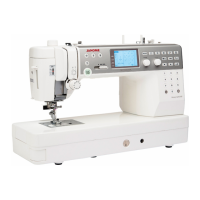
| Type | Computerized Sewing Machine |
|---|---|
| Stitch Options | 200 |
| Stitch Count | 200 |
| Maximum Stitch Width | 9 mm |
| Maximum Stitch Length | 5 mm |
| Buttonhole Styles | 11 |
| Needle Positions | 91 |
| Display | LCD |
| Free Arm | Yes |
| Automatic Thread Cutter | Yes |
| Weight | 24.3 lbs (11 kg) |
| Speed Control Slider | Yes |
| Start/Stop Button | Yes |
| Needle Up/Down | Yes |
| Lighting | LED |
| Knee Lifter | Yes |
| Needle Threader | Yes |
| LCD Screen | Yes |
| Built-in Memory | Yes |
| USB Port | Yes |
| Maximum Sewing Speed | 1000 spm |
