EasyManua.ls Logo

Jarvis Buster V User Manual

Jarvis Buster V
16 pages
To Next Page IconTo Next Page
Page #1 background imageLoading...
Page #1 background image
TABLE OF
CONTENTS Page.........................
Buster V Band Saw
460/230V--60Hz 4006033..........
380/220V--50Hz 4006057..........
Spring Balancer 4042052................
Air Balancer (4 feet overall length) 4042016
Air Balancer (20 feet overall length) 4042020
Standard Blade (127 in) 1023159.........
Cut Tooth Blade (127 in) 1023338........
JET Blade (127 in) 1023620.............
Safety Messages to Employer and
Safety Director 2...................
Safety Messages to Operators,
Maintenance and Cleanup Personnel 3
Parts Diagram and List 4............
Specifications 10...................
Installation Instructions 10...........
Operation Instructions 12............
Maintenance Instructions 13.........
Motor Wiring Diagrams 15...........
PRODUCTS CORPORATION
33 ANDERSON ROAD, MIDDLETOWN, CONNECTICUT 06457-4926
UNITED STATES OF AMERICA EMAIL.
jarvis.products.corp@snet.net
TEL. 860-347-7271 FAX. 860-347-6978 WWW.jarvisproducts.com
Model Buster V
Beef Splitting Band Saw
EQUIPMENT
SELECTION Ordering No..............
®
JARVIS
6206002;::::
Question and Answer IconNeed help?

Do you have a question about the Jarvis Buster V and is the answer not in the manual?

Jarvis Buster V Specifications

General IconGeneral
BrandJarvis
ModelBuster V
CategorySaw
LanguageEnglish

Summary

Safety Guidelines

Safety Directives for Employers

Guidelines for employers and safety directors on tool usage and safety protocols.

Operator and Personnel Safety

Instructions for safe operation, maintenance, and cleanup procedures for personnel.

Parts Identification and Diagrams

Idler End Parts and Diagram

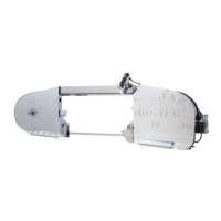
Diagram and list of parts for the idler end of the band saw.

Drive End Parts and Diagram

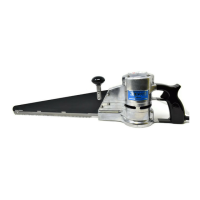
Diagram and list of parts for the drive end of the band saw.

Assemblies and Motor Details

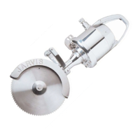
Diagrams and parts for torque knob, blade guides, motor, and gear cover assemblies.

Hanger and Handle Details

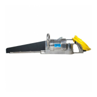
Diagrams and parts for hanger, control, and handle assemblies.

Electric and Rear Handle Details

Diagrams and parts for electric handles and rear handle assembly.

Electric Motor Details

Diagram and list of parts for the electric motor.

Control Box Details

Diagram and list of parts for the electric control box assembly.

Technical Specifications

Installation Guide

Control Box and Wiring Setup

Instructions for installing the electrical control box and wiring.

Motor Wiring and Balancer Setup

Steps for wiring the motor and installing the balancer.

Operation Instructions

Pre-Operation Checks

Performing dual anti-tie down control tests and balancer adjustments.

Cutting Procedure

Step-by-step guide for performing cuts on beef.

Maintenance Procedures

Daily Maintenance

Procedures for daily cleaning and checking blade guides.

Weekly and Periodic Maintenance

Weekly torque knob cleaning and necessary blade/wheel checks.

Motor Wiring Diagrams

Nine-Wire Motor Hook-up Diagram

Wiring diagram for nine-wire motor configurations.

Six-Wire Motor Hook-up Diagram

Wiring diagram for six-wire motor configurations.

Related product manuals