EasyManua.ls Logo

Jarvis SEC 230 User Manual

Default Icon
20 pages
To Next Page IconTo Next Page
Page #1 background imageLoading...
Page #1 background image
TABLE OF
CONTENTS Page.
. . . . . . . . . . . . . . . . . . . . . . . . . . .
Models SEC 230 and 230–LN
with DC Brake page 11.
. . . . . . . . . .
with Mechanical Brake page 13.
. . .
Blade (230mm)
Standard, 130 Teeth 1023286.
. . . . .
Skip tooth, 72 Teeth 1023387.
. . . . . .
Noise Reduction, Skip Tooth 1023299
Noise Reduction, 60 Teeth 1023348.
Balancer 4042004
. . . . . . . . . . . . . . . . . . . .
PRODUCTS CORPORATION
33
ANDERSON ROAD, MIDDLET
OWN, CONNECTICUT 06457-4926
UNITED ST
A
TES OF AMERICA
TEL. 860-347-7271 F
AX. 860-347-6978
Model
SEC 230 and 230–LN
Circular Breaking Saw
EQUIPMENT
SELECTION Ordering No..
. . . . . . . . . . . .
Notice to Employer and Safety
Director 2.
. . . . . . . . . . . . . . . . . . . . . . . . . . . . . . . .
Notice to Operators, Maintenance
and Cleanup Personnel 3.
. . . . . . . . . . . . . . . . . .
Parts Diagram and List 4.
. . . . . . . . . . . . . . . . . . .
Wiring Diagrams 13.
. . . . . . . . . . . . . . . . . . . . . . .
Special Tools 15.
. . . . . . . . . . . . . . . . . . . . . . . . . .
Specifications 16
. . . . . . . . . . . . . . . . . . . . . . . . . . .
Installation Instructions 16.
. . . . . . . . . . . . . . . . . .
Operation Instructions 17.
. . . . . . . . . . . . . . . . . . .
Maintenance Instructions 17.
. . . . . . . . . . . . . . . .
Dual Trigger Model
JARVIS
6204008:::
Question and Answer IconNeed help?

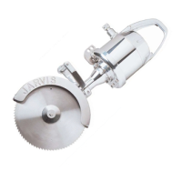
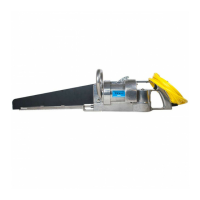
Do you have a question about the Jarvis SEC 230 and is the answer not in the manual?

Jarvis SEC 230 Specifications

General IconGeneral
BrandJarvis
ModelSEC 230
CategorySaw
LanguageEnglish

Summary

Equipment Selection

Models SEC 230 and 230-LN with DC Brake

Part numbers for models with DC brake.

Models SEC 230 and 230-LN with Mechanical Brake

Part numbers for models with mechanical brake.

Blade (230mm)

Ordering information for 230mm blades.

Balancer

Ordering information for the balancer.

Notice to Employer and Safety Director

Notice to Operators, Maintenance and Cleanup Personnel

Parts Diagram and List (Figure A)

Parts Diagram and List (Figure B)

Parts Diagram and List (Figure C)

Control Box Assembly (Figure E)

Control Box Assembly (Figure F)

Control Box Assembly (Figure G)

Control Box Assembly (Figure H)

Parts List

Parts List

Parts List and Wiring Diagram

Wiring Diagrams

460V Wiring Diagram

Electrical wiring schematic for 460V models.

380V Wiring Diagram

Electrical wiring schematic for 380V models.

Wiring Diagram

42V Wiring Diagram

Electrical wiring schematic for 42V models.

Special Tools

Recommended tools for assembly/disassembly.

Specifications

Installation Instructions

Operation Instructions

Maintenance Instructions

Circular Blade Removal

Steps to remove the circular blade from the saw.

Circular Blade Installation

Steps to install the circular blade onto the saw.

Right Angle Gear Housing Disassembly

Steps to disassemble the right angle gear housing.

Maintenance Instructions

Right Angle Gear Housing Assembly

Steps to reassemble the right angle gear housing.

Motor Disassembly

Steps to disassemble the motor unit.

Rear Handle Disassembly for DC Brake Models

Steps to disassemble the rear handle for DC brake models.

Maintenance Instructions

Rear Handle Disassembly for Mechanical Brake Models

Steps to disassemble the rear handle for mechanical brake models.

Front Handle Trigger Disassembly

Steps to disassemble the front handle trigger assembly.

Front Handle Trigger Assembly

Steps to reassemble the front handle trigger.

Related product manuals