C2 Series 3
3. Major Operation Controls
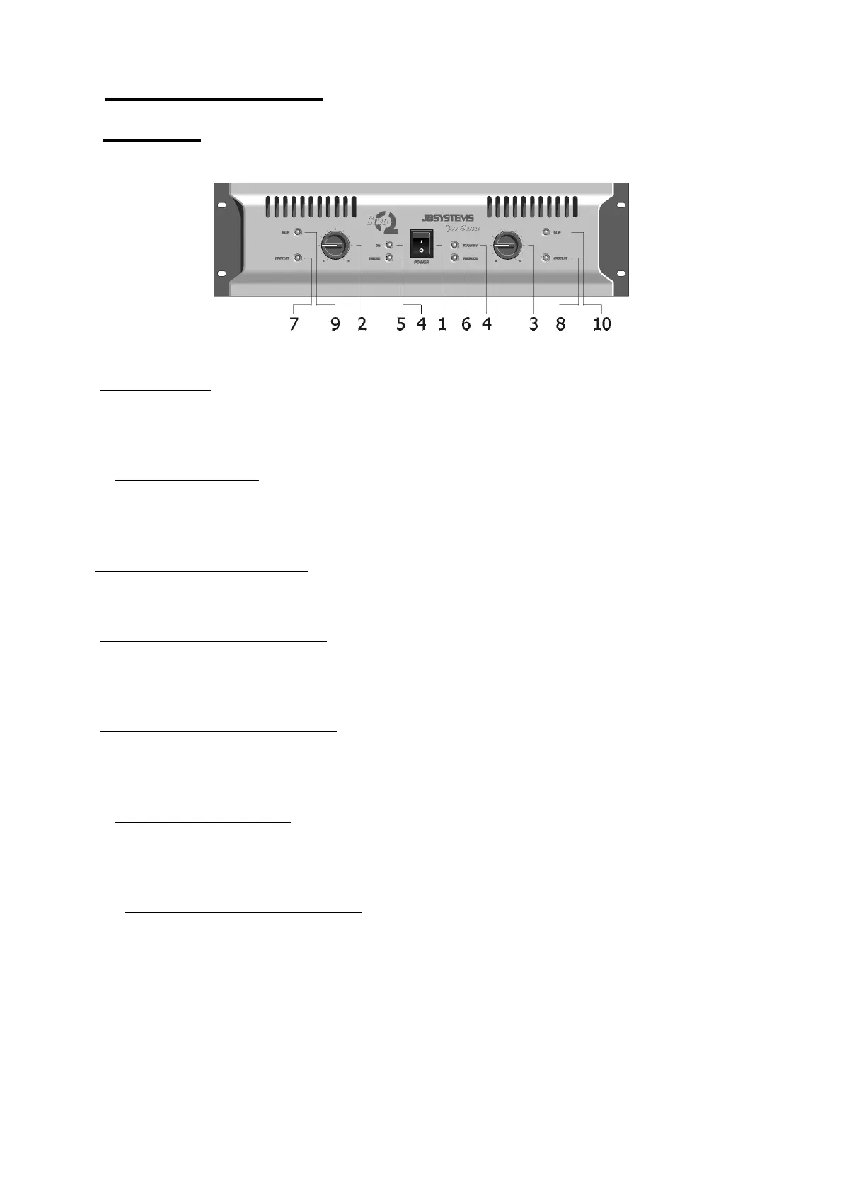
A. Front Panel
1. Power ON/OFF
With this switch, you turn the amplifier on. You will note a brief delay in the switching on,
due to the soft start.
2/3. Input Level Control
With these rotary VR’s, you can adjust the input level of each side.
In bridge or parallel mode, only the left VR is active.
4. Power ON Indicator (green)
Indicates that the amplifier is on.
5. Bridge Mode Indicator (green)
Indicates that the amplifier is working in bridge mode. In this case only the left channel
needs an input signal.
6. Parallel Mode Inidicator (green)
Indicates that the amplifier is running in parallel mode. The input signal must only be
applied to the left channel.
7/8. Protection LED (yellow)
The leds light up when the amplifier is overheated (thermal protection) or when
something is wrong with the amplifier.
9/10. Peak Level (clip) Indicator (red)
These leds will light up in two situations:
a. When the output signal has reached its maximum level, the LED will light. This goes
with a distortion of the audio signal. When this occurs, reduce the input level.
b. When you have an input signal and the clip led lights continuously, it means that
you have a short circuit on the output. Please turn of the amplifier and check out
the problem on the load.
 Loading...