"correct"polarity in
such
a
case
will
be
that
which yields
the most natural quality
with
a variety of program material.
6.
Once proper
polarity
among the transducers
of a loudspeaker system has been determined, other
loudspeaker systems in the installation (assuming
they are the same model) may be connected
accordingly.
Selecting
the Low Frequency
High-Pass
Filter Options
As
described in the Installation Section of this
manual,
the 5234A provides for low frequency
high-pass
contouring
by use of binary DIP switches.
While the
method
of setting these switches was
discussed,
it remains to treat the reasons for
choosing various settings.
In the most basic terms, one can select
flat
response
(no rolloff), or a 12 dB per octave roll-
off below 20 Hz, 30 Hz or 40 Hz. While the specific
filter
characteristics can be further modified, in
general the major purpose of high-pass
filtering
is
to remove subsonic signal energy below the lowest
useable
loudspeaker frequency.
Without
high-pass
filtering, subsonic signal content can waste amplifier
power (lowering the available headroom), and in-
duce
distortion
in audible regions by
modulating
the higher
bass
and midrange frequencies.
One of the special features of the 5234A is the
6
dB boost at 20 Hz, 30 Hz or 40 Hz selectable
with
the DIP switches (the Q=2 setting). This
moderate boost equalization, coupled
with
the
high-pass filtering, can
often
improve the acoustical
response
of a sound system.
The
use of the 6 dB boost/high-pass
filter
option
maximizes
the useful low frequency acoustic
output
while minimizing cone excursions
both
in and out
of the system operating range. The use of this
option
requires certain precautions, and care should
be taken not to exceed the power ratings of the
system.
Bear
in
mind
that
the 6 dB of boost results
in a four-times increase in power
from
the amplifier
to the loudspeaker system. However, this boost is
restricted to the octave just above the system's
lower
cutoff.
The boost/high-pass
filter
function should
normally be applied to vented box
systems,
set to
the box tuning frequency. The boost/high-pass
filter
can be used
with
closed-box (sealed) loud-
speaker
systems, but because of the
high
cone
excursions
of these systems near
cutoff,
caution
must be taken so
that
the cones do not
"bottom
out"
during
high
level
passages.
In general,
for sealed box systems it is better to use one of
the high-pass
filter
settings
that
produce a
rolloff
without
a peak
(e.g.,
with
a Q 0.707). If it is desir-
able
that
the loudspeaker system have a slight peak
near
an acoustic
cutoff
of 30 Hz, the 5234A's
slightly underdamped
rolloff
(Q=0.84) may be
selected.
Suggestions
for JBL Professional Series Products
1.
Generally, JBL studio monitors should have
high-pass
filtering
at 30 Hz.
2.
Sound reinforcement systems tuned to 40 Hz
should use 40 Hz high-pass filtering. This includes
most 4500 series enclosures and 4600 systems.
3.
For very low crossover frequency points in
subwoofer applications, monaural,summing of the
low frequency
outputs will
tend to cancel extrane-
ously generated, oppositely polarized low frequency
signals
such as turntable rumble, disc warp and
acoustic
feedback. Therefore, setting the DIP
switches
for a monaural LOW
output
can increase
the maximum usable acoustic
output
level.
4.
The 6 dB boost/high-pass
filter
option
may
be used
with
any JBL Professional
Series
system
when required to
flatten
and extend the low-
frequency response, provided
that
the
filter
frequency is appropriately chosen.
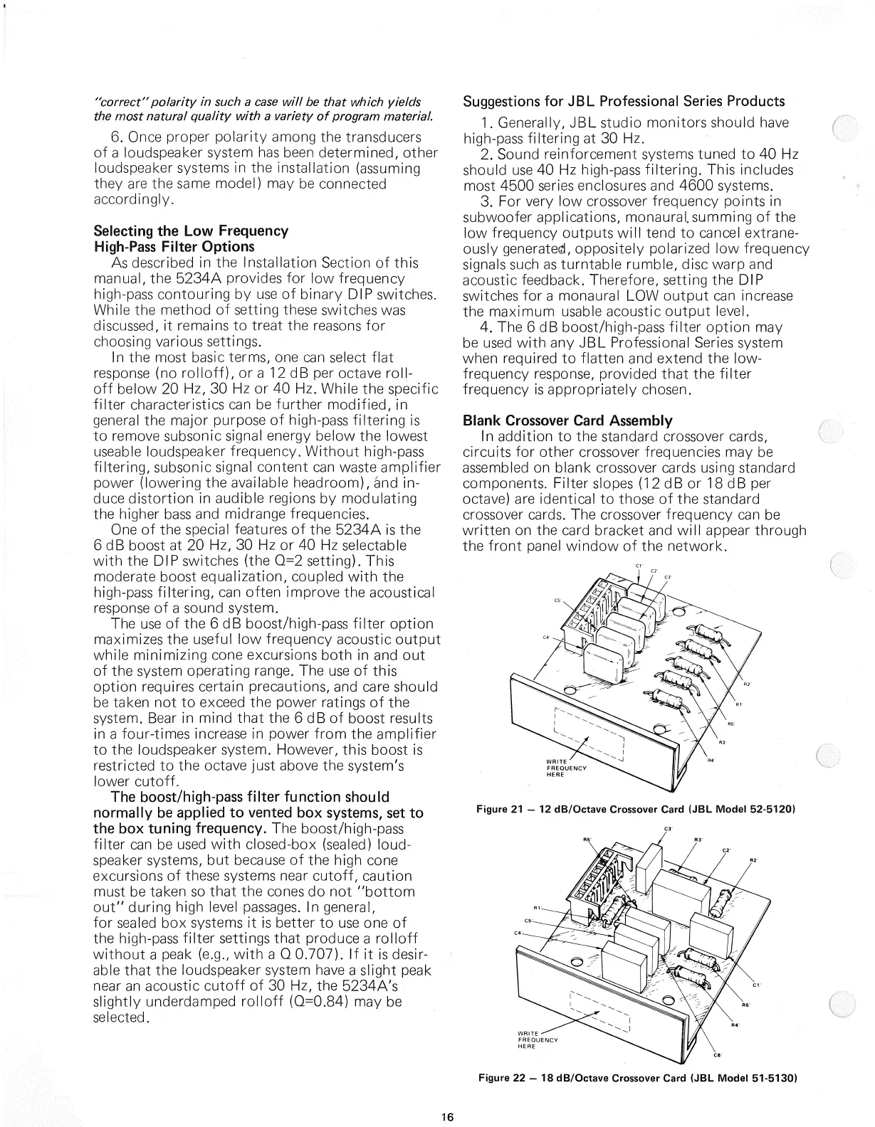
Blank
Crossover Card Assembly
In
addition
to the standard crossover cards,
circuits for other crossover frequencies may be
assembled
on blank crossover cards using standard
components. Filter slopes (12 dB or 18 dB per
octave)
are identical to those of the standard
crossover
cards. The crossover frequency can be
written
on the card bracket and
will
appear
through
the
front
panel window of the network.
Figure
21 - 12 dB/Octave Crossover Card (JBL
Model
52-5120)
Figure
22 - 18 dB/Octave Crossover Card (JBL
Model
51-5130)
16