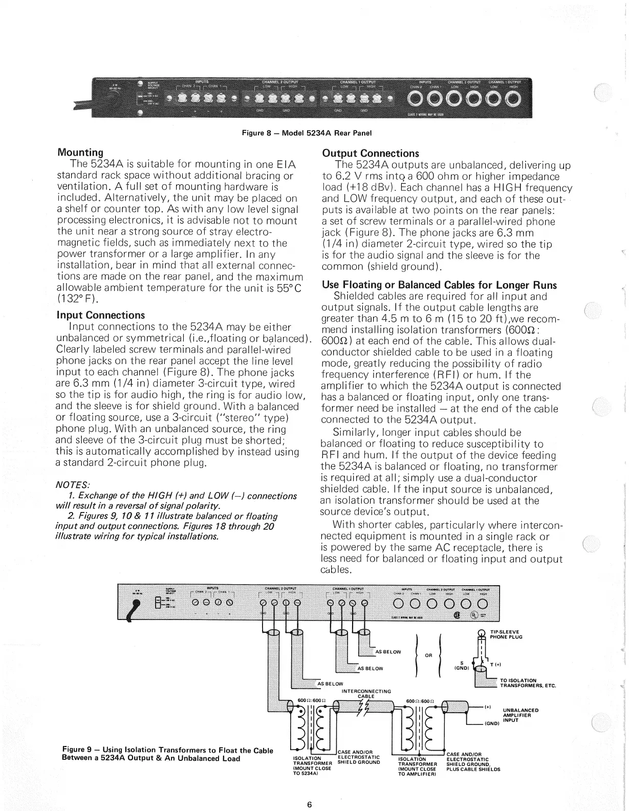
Figure
8 -
Model
5234A Rear Panel
Mounting
The
5234A is suitable for
mounting
in one EIA
standard rack space
without
additional bracing or
ventilation. A
full
set of
mounting
hardware is
included. Alternatively, the
unit
may be placed on
a
shelf or counter top. As
with
any low level signal
processing
electronics, it is advisable not to mount
the
unit
near a strong source of stray electro-
magnetic fields, such as immediately next to the
power transformer or a large amplifier. In any
installation, bear in mind that all external connec-
tions are made on the rear panel, and the maximum
allowable ambient temperature for the
unit
is 55°C
(132°F).
Input Connections
Input connections to the 5234A may be either
unbalanced or symmetrical (i.e.floating or balanced)
Clearly
labeled screw terminals and parallel-wired
phone
jacks
on the rear panel accept the line level
input
to each channel (Figure 8). The phone
jacks
are
6.3 mm (1/4 in) diameter 3-circuit type, wired
so
the tip is for audio high, the ring is for audio low,
and the sleeve is for shield ground. With a balanced
or
floating
source, use a 3-circuit ("stereo" type)
phone plug. With an unbalanced source, the ring
and sleeve of the 3-circuit plug must be shorted;
this is automatically accomplished by instead using
a
standard 2-circuit phone plug.
NOTES:
1.
Exchange
of the HIGH (+) and LOW (-) connections
will
result in a
reversal
of signal polarity.
2.
Figures
9, 10 & 11 illustrate balanced or floating
input and output connections.
Figures
18 through 20
illustrate wiring for typical installations.
Output Connections
The
5234A outputs are unbalanced, delivering up
to 6.2 V rms
into
a 600 ohm or higher impedance
load (+18 dBv).
Each
channel has a HIGH frequency
and LOW frequency
output,
and each of these
out-
puts is available at two points on the rear panels:
a
set of screw terminals or a parallel-wired phone
jack
(Figure 8). The phone
jacks
are 6.3 mm
(1/4
in) diameter 2-circuit type, wired so the tip
is
for the audio signal and the sleeve is for the
common (shield ground).
Use
Floating or Balanced Cables for Longer
Runs
Shielded
cables are required for all
input
and
output
signals. If the
output
cable lengths are
greater than 4.5 m to 6 m (1 5 to 20 ft),we recom-
mend installing isolation transformers (600£2:
60012)
at each end of the cable.
This
allows dual-
conductor shielded cable to be used in a
floating
mode, greatly reducing the possibility of radio
frequency interference (RFI) or hum. If the
amplifier to which the 5234A
output
is connected
has
a balanced or
floating
input,
only one trans-
former need be installed — at the end of the cable
connected to the 5234A
output.
Similarly,
longer
input
cables should be
balanced
or
floating
to reduce susceptibility to
RFI
and hum. If the
output
of the device feeding
the 5234A is balanced or floating, no transformer
is
required at all; simply use a dual-conductor
shielded cable. If the
input
source is unbalanced,
an
isolation transformer should be used at the
source
device's
output.
With shorter cables, particularly where intercon-
nected equipment is mounted in a single rack or
is
powered by the same AC receptacle, there is
less
need for balanced or
floating
input
and
output
cables.
Figure
9 — Using Isolation Transformers to Float the Cable
Between a 5234A Output & An Unbalanced Load
TIP-SLEEVE
PHONE
PLUG
' TO ISOLATION
.
TRANSFORMERS,
ETC.
UNBALANCED
AMPLIFIER
INPUT
6
AS
BELOW
AS
BELOW
AS
BELOW
INTERCONNECTING
CABLE
ISOLATION
TRANSFORMER
(MOUNT
CLOSE
TO
5234A)
CASE
AND/OR
ELECTROSTATIC
SHIELD
GROUND
ISOLATION
TRANSFORMER
(MOUNT
CLOSE
TO
AMPLIFIER)
CASE
AND/OR
ELECTROSTATIC
SHIELD
GROUND,
PLUS
CABLE
SHIELDS
600
SI:
600
SI
OR