TABLE
OF
CONTENTS
ARCHITECTURAL
SPECIFICATIONS
ARCHITECTURAL
SPECIFICATIONS
2
PRODUCT
SPECIFICATIONS
3
Electrical
3
Physical
3
INSTALLATION
4
Installation of Standard Crossover Frequency Modules 4
Programming the internal High-Pass Filters 5
Mounting
6
Input
Connections 6
Output
Connections 6
Use
Floating or Balanced Cables for Longer Runs 6
AC
Power Connection and Line Voltage Conversion 7
Protection of Compression Drivers 8
SETUP
AND
OPERATION
9
General
Applications 9
Typical Systems Employing the 5234A 9
A
Safety Procedure for I
nitial
Powering Up of The System 14
Level
Control
Adjustment
14
System
Phasing and Signal Polarity 14
Selecting the Low Frequency High-Pass Filter Options 16
Blank Crossover Card Assembly 16
PARTS
LIST
18
SCHEMATIC
DIAGRAM 19
LIST
OF
ILLUSTRATIONS
Figure Description
1
Total Harmonic
Distortion
3
2
5234A Low Frequency
Cutoff
Characteristics 3
3
Screw Removal to Lift Off the
Bottom
Cover 4
4
Identification
of
Major
Components Inside 5234A 4
5
Crossover Card
Mounting
Alignment
4
6
One of the Two Programming DIP Switches 5
7 DIP Switch Programming and Resultant Low 5
Frequency
Cutoff
Characteristics
8
Model
5234A
Rear
Panel 6
9
Using Isolation Transformers to Float the Cable 6
Between a 5234A
Output
and an Unbalanced
Load
10 Using an Isolation Transformer to Float (or 7
Balance)
the Cable Between a 5234A
Output
and a Floating (or Balanced) Load
11 Using an Isolation Transformer to Float the 7
I
nput
Cable to the 5234A
12 Conventional Two-Way System
(Passive
Network) 9
13
Conventional Three-Way System
(Passive
Network) 9
14 Dual Channel Two-Way System (Biamplified) 9
15
Single Channel Three-Way System (Triamplified) 10
16 Dual Channel Two-Way System
with
Monaural 10
Subwoofer(s)
17 Combining Electronic and
Passive
Frequency 10
Dividing
Networks
18
Wiring
Diagram for Biamplified System 11
19
Wiring
Diagram for Triamplified System 12
20
Wiring
Diagram for Two-Way System
with
13
Monaural Subwoofer(s)
21 12 dB/Octave Blank Crossover Card (JBL 16
Model
52-5120)
with
Component Designations
22 18 dB/Octave Blank Crossover Card (JBL 16
Model
51-5130)
with
Component Designations
Table
1
Maximum Values for Low Frequency 8
Attenuating
Protection Capacitors
2
JBL Protection Capacitors for Compression Drivers 8
3
12 dB/Octave Crossover Card Component Values 17
4 18 dB/Octave Crossover Card Component Values 17
WARNING: To prevent
fire
or shock hazard, do not expose
this
unit
to rain or moisture.
The
electronic frequency
dividing
network
shall
contain two channels, each
with
low-level active
filters
that
separate the
program
into
low and
high
frequency bands at designated crossover frequency
points.
Each
channel shall have a transformerless,
differential
amplifier
input
and separate
buffer
amplifiers for its low and
high
frequency
outputs.
Input
and
output
connections shall be made via
either
1
/4 inch (6.3 mm)
phone
jacks or screw
terminals
provided
on the unit's rear panel.
Crossover
frequency selection shall be accom-
plished by
internally
mounted
plug-in
circuit
modules, one per channel.
Each
module
shall be
designated
with
the crossover frequency,
printed
in such a
position
as to be easily read
through
a
window
in the unit's
front
panel. The designated
crossover frequency shall be the
point
at which
the slopes of the pass band curves cross, and where
each
is 3 dB
down
from
the average pass band
output
level; this
point
shall be
within
± 10% of
the designated frequency. A variety of modules
shall be available, not
only
with
different
crossover
frequency points, but also
with
12 dB or 18 dB
per octave
filter
slopes. Blank
plug-in
modules shall
be available,
allowing
for the
installation
of suitable
capacitors and resistors to achieve custom crossover
frequency points.
In
addition,
internally
switch selectable low
frequency equalization and subsonic
filtering
shall
be
provided
for each channel, enabling low fre-
quency response to be
optimized
while
blocking
subsonic energy
below
the lowest usable speaker
frequency. These dual in line switches shall allow
the
following
programmable
options,
all
with
12 dB per octave slope rates (except the
flat
response setting):
a.
Flat frequency response (e.g., no L.F. cut-
off filter).
b. 20 Hz
high
pass
filter,
Q = 0.707 (Butter-
worth).
c.
20 Hz
high
pass
filter,
Q = 2 (6 dB
boost
at 20 Hz).
d. 30 Hz
high
pass
filter,
Q = 0.54.
e.
30 Hz
high
pass
filter,
Q = 0.84.
f. 30 Hz
high
pass
filter,
Q = 2 (6 dB
boost
at 30 Hz).
g. 40 Hz
high
pass
filter,
Q = 0.707 (Butter-
worth).
h. 40 Hz
high
pass
filter,
Q = 2 (6 dB
boost
at 40 Hz).
The
internal switching shall also allow
both
channels'
low frequency
outputs
to be
combined
into
a monaural signal which,
with
an
appropriate
crossover frequency, is suitable for
driving
a sub-
woofer
channel while the
high
frequency
outputs
drive a
full-range
stereo speaker system.
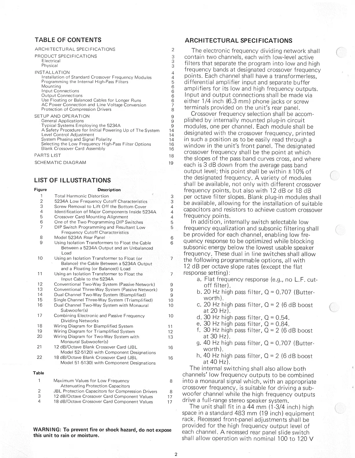
The
unit
shall fit in a 44 mm (1-3/4 inch)
high
space
in a standard 483 mm (19 inch)
equipment
rack.
Recessed
front-panel
adjustments shall be
provided
for the
high
frequency
output
level of
each
channel. A recessed rear panel slide switch
shall allow
operation
with
nominal
100 to 120 V
2