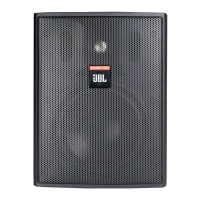
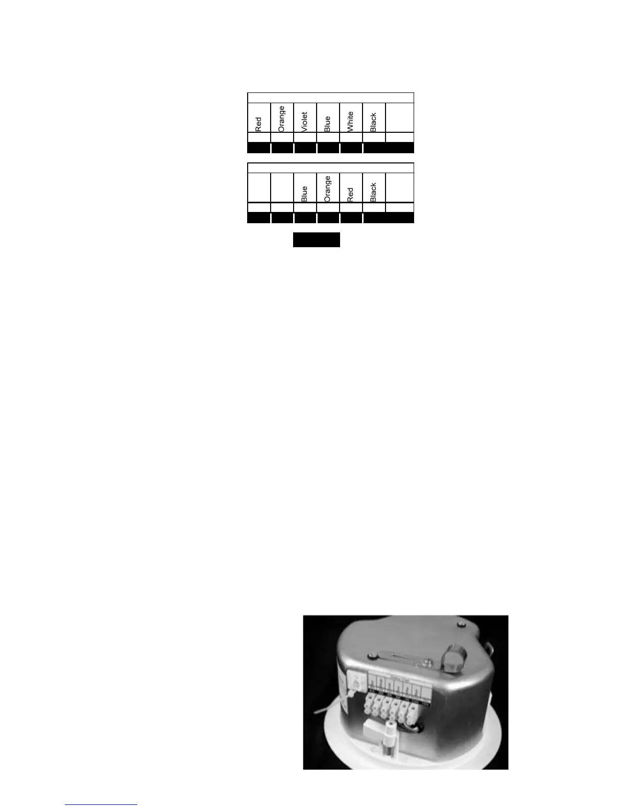
N.C. 9W 4W 2W 1W Com 100V
For Control 24CT Micro and the Control 24CT MicroPlus, connect the negative input to
the "Common" terminal and connect the positive input to the appropriate tap. The input
pins correspond to the taps of the transformer indicated on the label above each connec-
tor. For example, if the system is being driven from a 70V Distributed Line, and the 2W
tap is the desired connection, the positive input would be made to the input marked "2W,
Violet." The negative connection would be made to the "Common" pin.
On the Control 24C Micro, low impedance version, connect the negative wire to the "-"
terminal and connect the positive wire to the "+" terminal.
All other pins are "No Connection."
Paralleling Input Terminals - It is common to run two sets of wires - one set is the
input to the speaker and the other is the feed to the next speaker. In this case, simply par-
allel the two sets of wires to the same terminals on the speaker's terminal block.
Guide to the Pins for Connection - The locking input connector contains 7 terminals,
as marked above the connector. The pin functions are listed on the label located on the
terminal cover plate.
Step 4 - Add included metal strain relief as necessary. The Control 24C/CT Micro and the
24CT MicroPlus are equipped with two locations where the installer can affix strain relief con-
nectors - one is on the back of backcan and one is on the side (for applications with shallow
access). The location of these two attachment points is shown on the Product Feature
Identification on Page 3. The installer can attach a wide variety of installer provided fittings to
these points if the included equipment is not adequate for the particular installation. Refer to
Figure 6 shows the strain relief INCLUDED with the Control 24C/CT Micro and Control 24CT
MicroPlus.
Figure 6:
Included Metal Strain Relief