Do you have a question about the JBL GTR-601 and is the answer not in the manual?
FCC and IC regulations for RF energy and digital apparatus operation.
Guidelines for safe installation, including antenna grounding.
Precautions for battery safety, replacement, and environmentally sound disposal.
Techniques to prevent damage from static electricity when handling components.
Precautions for servicing, component replacement, and insulation checks.
Procedure to measure leakage current to ensure electrical safety.
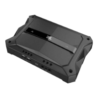
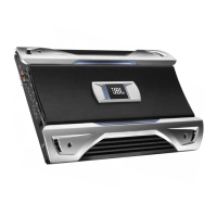
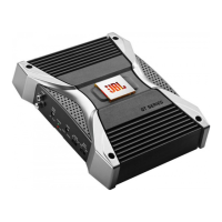
Detailed specifications including power output, frequency response, and dimensions.
Diagram illustrating the main functional blocks of the amplifier.
Schematic detailing the power supply and distribution circuits.
Schematic diagram of the pre-amplifier section.
Schematic for the main amplifier output stage and related components.
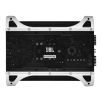
Top view layout showing component placement on the amplifier board.
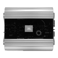
Bottom view layout showing component placement on the amplifier board.
Exploded view and list of parts with P/Ns for assembly and replacement.
Visual guide to packaging contents and assembly steps.
Comprehensive list of spare parts with P/Ns and descriptions for replacement.
| Amplifier class | D |
|---|---|
| Signal-to-Noise Ratio (SNR) | 80 dB |
| Number of amplifier channels | 4 channels |
| RMS power output per channel (2 Ohm) | 600 W |
| RMS power output per channel (4 Ohm) | 400 W |
| Product color | Black |