Do you have a question about the JBL L212 and is the answer not in the manual?
This manual is intended for JBL-approved service technicians for maintenance and servicing of the L212.
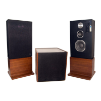
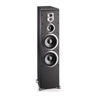
The L212 system description covers physical and circuit aspects, outlining the three main modules of the loudspeaker system.
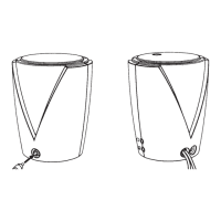
Details the pedestal-mounted, 3-way loudspeaker enclosures, including their physical layout and components.
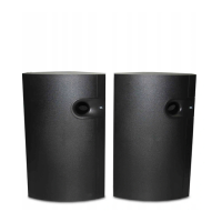
Explains the interrelationship of networks and components via block diagrams, focusing on the Ultrabass and main speaker systems.
Recommends returning faulty subassemblies to JBL or authorized dealers, but provides guidance for in-house repairs.
Lists essential tools required for diagnosing and isolating problems within the L212 system.
Provides step-by-step instructions for safely accessing internal components of the Ultrabass and main speaker enclosures.
Outlines general rules and specific steps for component replacement, including soldering techniques and thermal compound use.
Details a logical, progressive manner for isolating problems to major assemblies or specific components using flow charts.
Provides specific troubleshooting steps for diagnosing issues within the Ultrabass module using a dedicated flow chart.
Describes the procedure for verifying DC offset voltage and amplifier performance parameters after component replacement.
Lists all components used in the L212 system, including part numbers, descriptions, and quantities for various circuits.
| Type | 3-way loudspeaker system |
|---|---|
| Impedance | 8 ohms |
| Bass Radiator | Passive radiator |
| Tweeter | 1" dome |
| Subwoofer | 12" subwoofer |
| Midrange Driver Size | 5" |
| Tweeter Type | Dome |
| Midrange | 5-inch driver |