17
Appendex A
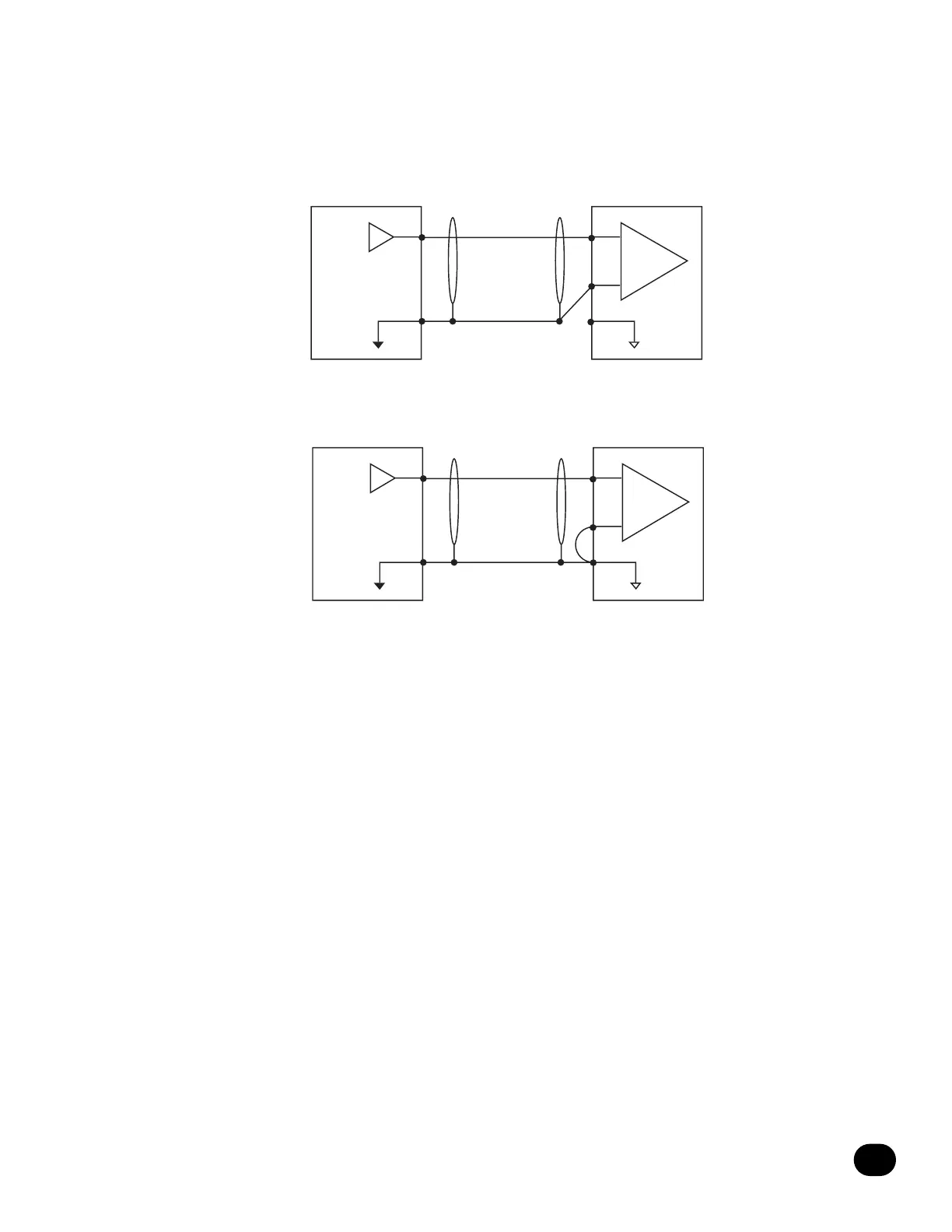
Diagram D details the connections using single conductor shielded cable with a Tip/Ring/Sleeve plug for the 6328P input. Single con-
ductor cable should be used as a last resort as it provides the greatest likelihood of problems. The "HOT" (+) signal should be connect-
ed to the tip of the Tip/Ring/Sleeve plug. The GROUND should be attached to the Ring of the Tip/Ring/Sleeve plug at the 6328P input.
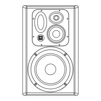
Diagram E details the connections using unbalanced cable and Tip/Sleeve connections to the 1/4" input. In this mode, the Ring and
Sleeve of the input are shorted by the plug automatically.