19
UK
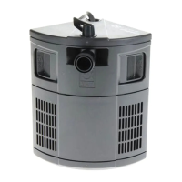
10 JBL ProFlora T3 CO
2
hose
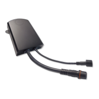
11 Connection cable for solenoid valve
12 JBL Test Kit permanent CO
2
plus pH CO
2
permanent test
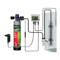
11.1 Step by step installation
1. First attach, where available, the extensions to the JBL Taifun CO
2
Passive Reactor (9)
according to the height of the aquarium.
Rinse the reactor in lukewarm water and place it vertically in the aquarium in a location with
a slight current of water. The upper edge should be approx. 2 cm under the surface of the
water. The slits of the individual modules should be as free as possible from obstruction
by plants or decorations.
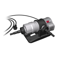
2. Installation of the bubble counter (8):
Select a suitable place to t the bubble counter where it can be easily observed. Install the
bubble counter (8). The bubble counter can either be attached using suction pads (e.g. to
the outside of the aquarium) or to a wall or surface of a piece of furniture with the enclosed
screws. Cut the C
2
hose (10) to the correct length and attach the free ends to the hose
screw connection of the bubble counter. Make sure the supply hose is attached to the
connection with the long pipe in the bubble counter. Unscrew the lid of the bubble counter
and ll it up to 2/3 with water before closing again. In case the check valve was demounted
during the opening, make sure that all parts are correctly reassembled (see drawing on the
separate packaging of the bubble counter).
Note: When installing without a bubble counter, a separate check valve, which is not
included in the set, must be mounted.
u501, u502, m501, m502:
Install the CO
2
permanent test (11) in the aquarium according to the enclosed instructions.
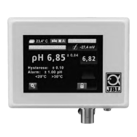
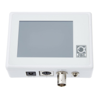
m503, m2003:
Select a suitable place to position the pH computer (7) where it can be easily observed.
Connect the solenoid valve of the pressure regulator (6) with the enclosed valve cable to
the connection “valve” of the pH computer (7). The connectors of the pH computer and
the plug connection of the valve cable are congured in such a way, that an incorrect
connection is not possible.
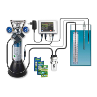
3. For the CO
2
storage bottle, select a place with a stable base that is out of the reach of
children (e.g. cabinet under the aquarium). Insert the m500 rellable storage bottle (1) into
the stand. The m2000 rellable storage bottle (2) and the disposable u500 storage bottle
(3) are free-standing. Position the bottle in the place selected.
4. Connect the pressure regulator to the storage bottle:
u501, u502 CO
2
kits:
Briskly screw the pressure regulator (5, 6) with the internal thread on the back onto the
external thread of the disposable storage bottle (3). After a few turns, a brief hissing noise
will be heard. Continue to turn briskly until you feel resistance. Then turn about half a turn
more until the tting is hand-tight. The left-hand pressure gauge now shows the bottle
pressure of about 60 bar and the right-hand pressure gauge shows the operating pressure
of about 1.5 bar. Close the adjusting screw by turning clockwise, if it is not already closed.
The m501, m502, m503, m2003 CO
2
kits: Screw the connecting nut on the back of the
pressure regulator (4, 6) onto the external thread of the bottle valve on the m500 (1) or
Space for purchase receipt: