About the Product
Operator Station
17 9831/1300-3 17
Operator Station
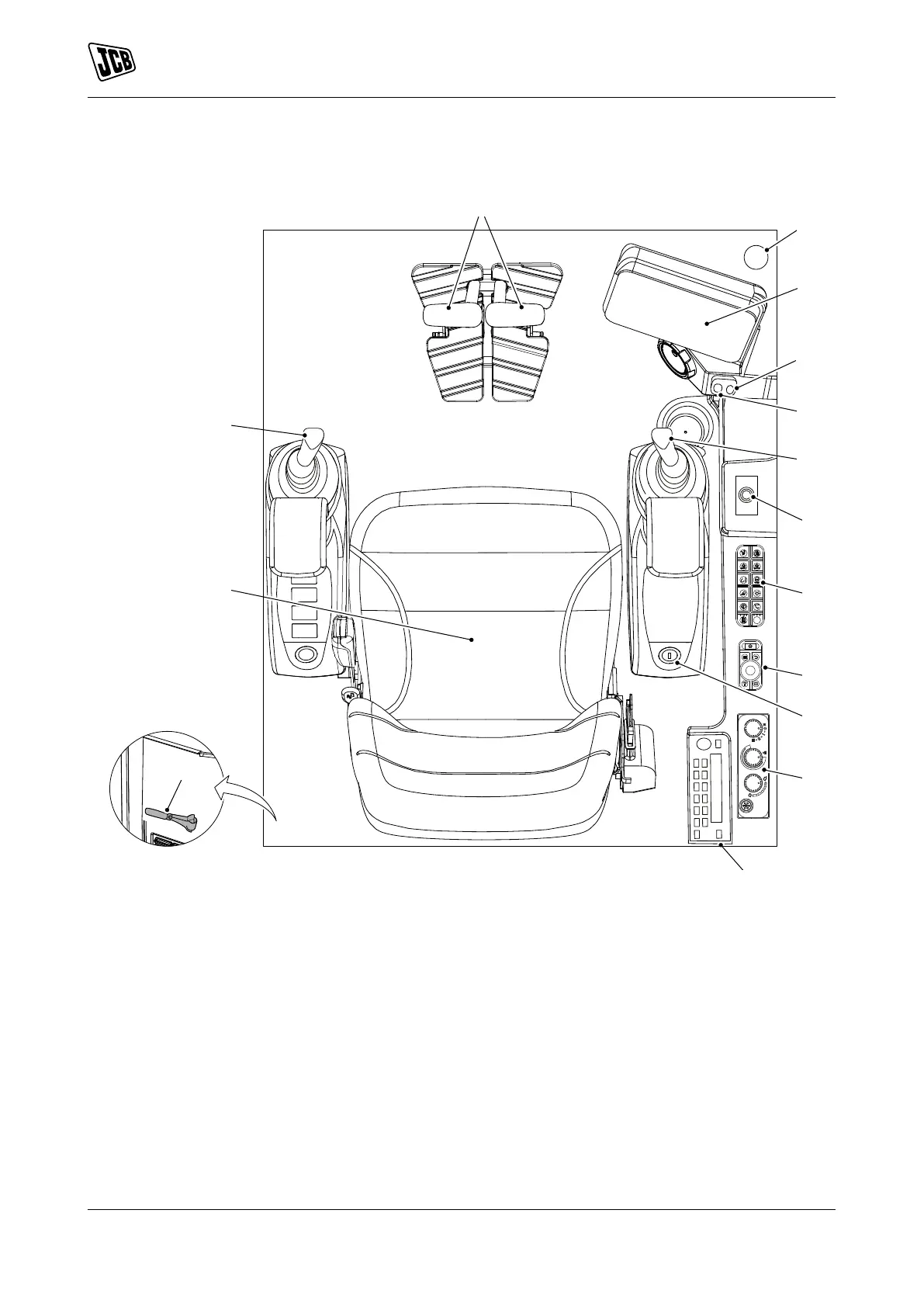
Component Locations
Figure 11.
A Track controls Refer to: Track Controls
(Page 61).
B Fire extinguisher (option)Refer to: Fire
Extinguisher (Page 93).
C Instrument panel Refer to: Instrument Panel
(Page 62).
D Auxiliary power socket Refer to: Auxiliary Power
Socket (Page 91).
E USB port F Excavator controlsRefer to: Excavator End
Controls (Page 76).
G Dozer blade control lever Refer to: Dozer Blade
Controls (Page 79).
H Switch panelRefer to: General (Page 20).
J Rotary switch panelRefer to: Instrument Panel
(Page 62).
K Ignition key switch Refer to: Ignition Switch
(Page 18).
L HVAC (Heating Ventilation Air Conditioning)
controls Refer to: Heating, Ventilating and Air-
Conditioning (HVAC) (Page 89).
M Radio (option)
N Glazing breaker Refer to: Emergency Exit
(Page 31).
P Operator seatRefer to: Operator Seat
(Page 41).